Control unit and control method for variable valve timing mechanism

a control unit and variable valve technology, applied in process and machine control, hybrid vehicles, instruments, etc., can solve the problems of low operation speed of each element in relatively low operating noise of the variable valve timing mechanism

Active Publication Date: 2013-08-20
TOYOTA JIDOSHA KK
View PDF19 Cites 2 Cited by
  • Summary
  • Abstract
  • Description
  • Claims
  • Application Information

AI Technical Summary

Benefits of technology

[0010]With the control unit and control method described above, when the target idle speed for the internal combustion engine is variably set based on the vehicle state (e.g. selected shift position or shift range), if the target idle speed is set to a value lower than the predetermined rotational speed and an occupant of the vehicle easily hears operating noise of the variable valve timing mechanism, the range, in which the valve phase is allowed to change, is restricted within the region in which the ratio of the change amount of the opening / closing timing (valve phase) with respect to the operation amount of the actuator is high. As a result, the valve phase is controlled within the phase region (first region) in which it is relatively difficult to transmit an external rotational force to the inside of the variable valve timing mechanism and the operation speed of each element in the variable valve timing mechanism is relatively low. Therefore, it is possible to make the operating noise of the variable valve timing mechanism relatively low so that the vehicle occupant does not easily hear the operating noise.
[0013]With the control unit and the control method described above, when the internal combustion engine is cold, it is possible to restrict the range, in which the valve phase is allowed to change when the internal combustion engine is idling, within the region (first region) where the speed reduction ratio is high and the valve timing can be maintained without accurately controlling the operation of the actuator, in consideration of the fact that there is a possibility that the valve phase cannot be changed by a sufficient amount by the variable valve timing mechanism due to an increase in friction when the internal combustion engine is cold. As a result, when the internal combustion engine, which has been idling, is brought to a standstill while the internal combustion engine is cold, it is possible to reliably place the valve phase within the first region when the engine stops. Therefore, it is possible to suppress a deviation of the actual valve phase from the phase used in the control, which is likely to occur when the engine is stopped.
[0015]With this configuration, it is possible to easily restrict the range, in which the valve phase is allowed to change when the internal combustion engine is idling, within the first region by setting the target value of the valve phase to a value within the restricted region.
[0017]With this configuration, when the valve phase, which is suitable for enhancement of the efficiency of combustion that takes place in the internal combustion engine when it is idling, is outside the first region, if the target idle speed is equal to or higher than the predetermined rotational speed and it is less likely for the vehicle occupant to hear the operating noise of the variable valve timing mechanism, the valve phase is controlled with higher priority given to enhancement of the combustion efficiency.
[0023]With the aspects of the invention described above, it is possible to appropriately control the valve phase when the internal combustion engine is idling, using the variable valve timing mechanism that is configured in such a manner that the ratio of the change amount of a valve phase with respect to the operation amount of the actuator (speed reduction ratio) changes based on the valve phase.

Problems solved by technology

As a result, the valve phase is controlled within the phase region (first region) in which it is relatively difficult to transmit an external rotational force to the inside of the variable valve timing mechanism and the operation speed of each element in the variable valve timing mechanism is relatively low.
Therefore, it is possible to make the operating noise of the variable valve timing mechanism relatively low so that the vehicle occupant does not easily hear the operating noise.

Method used


Image

  • Control unit and control method for variable valve timing mechanism
  • Control unit and control method for variable valve timing mechanism
  • Control unit and control method for variable valve timing mechanism

Examples


Embodiment Construction

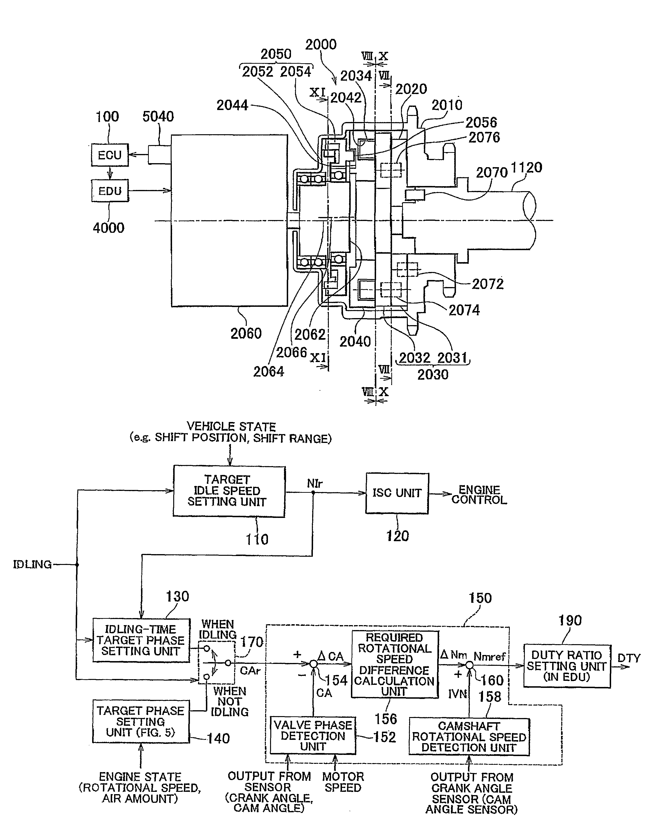
[0043]Hereafter, an embodiment of the invention will be described with reference to the accompanying drawings. In the following description, the same or corresponding elements will be denoted by the same reference numerals, and the descriptions concerning the elements having the same reference numerals will be provided only once below.

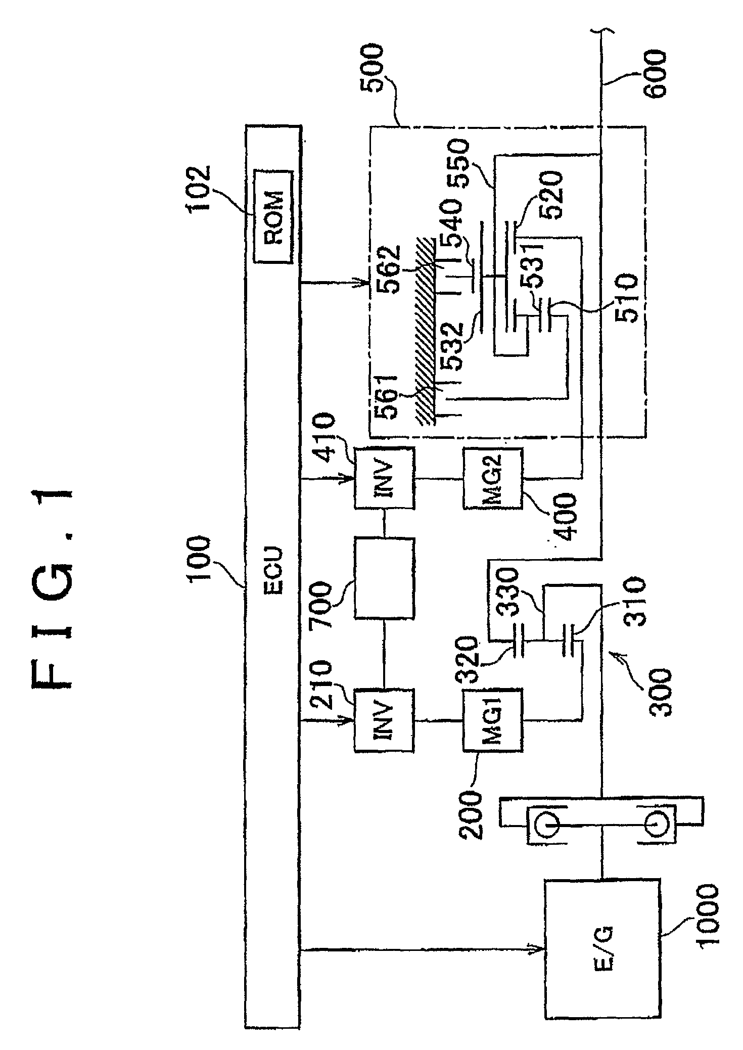
[0044]A power train of a hybrid vehicle provided with a control unit according to an embodiment of the invention will be described with reference to FIG. 1. The control unit according to the embodiment of the invention is implemented when an ECU (Electronic Control Unit) 100 executes a program stored in a ROM (Read Only Memory) 102 of the ECU 100. The ECU 100 may be divided into multiple ECUs. The program that is executed by the ECU 100 may be recorded in a CD (Compact Disc) or a DVD (Digital Versatile Disc), and distributed to the market.

[0045]As shown in FIG. 1, the power train is formed mainly of an engine 1000, a first MG (Motor Generator) 200, a p...


PUM


Abstract

An idling-time target phase setting unit (130) variably sets a target phase based on a target idle speed that is set by a target idle speed setting unit. (110) Especially, when the target idle speed is lower than a predetermined rotational speed and operating noise of a variable valve timing mechanism (2000) is easily heard by, for example, a driver, the.idling-time′ target phase setting unit (130) sets the target phase so that a range, in which the valve phase is allowed to change, is restricted within a phase region where a speed reduction ratio is high and the operating noise is relatively low.

Description

BACKGROUND OF THE INVENTION[0001]1. Field of the Invention[0002]The invention relates generally to a control unit and control method for a variable valve timing mechanism. More specifically, the invention relates to a variable valve timing control that is executed when an internal combustion engine is idling.[0003]2. Description of the Related Art[0004]A variable valve timing (VVT) mechanism that changes the phase (i.e., crank angle), at which an intake valve or an exhaust valve is opened / closed, based on the engine operating state has been used. Such variable valve timing mechanism changes the phase of the intake valve or the exhaust valve by rotating a camshaft, which opens / closes the intake valve or the exhaust valve, relative to, for example, a sprocket. The camshaft is rotated hydraulically or by means of an actuator, for example, an electric motor. It is more difficult to obtain the torque for rotating the camshaft, when the camshaft is rotated by the electric motor than when ...

Claims


Application Information

Patent Timeline
Patent Type & Authority Patents(United States)
IPC IPC(8): F02D13/04B60K31/02
CPCF01L1/352B60L3/0023B60L15/20B60L2240/421B60L2240/423B60L2240/441B60L2240/443B60L2240/445B60L2240/486B60L2240/507B60L2270/12B60L2270/145B60L50/16B60L50/61F02D13/02Y02T10/12Y02T10/62Y02T10/64Y02T10/70Y02T10/7072Y02T10/72F01L1/34
Inventor HATTORI, MASAYOSHIABE, TSUKASA
Owner TOYOTA JIDOSHA KK
Why Eureka
Try Eureka