Slot seal

a slot and sealing technology, applied in the field of slot sealing, can solve the problems of affecting lift performance, voids can be opened in the lower aerodynamic surface of the aerofoil, and it is not practicable to cut back the supporting structure, etc., and achieve the effect of improving sealing

Inactive Publication Date: 2013-08-20
AIRBUS OPERATIONS LTD
View PDF5 Cites 8 Cited by
  • Summary
  • Abstract
  • Description
  • Claims
  • Application Information

AI Technical Summary

Benefits of technology

[0011]The present invention is advantageous in that a slot at the edge of an aircraft panel, necessary to provide clearance to a structural support when the panel is moved, can be sealed by a resilient seal member when this clearance is not required. The resilient seal member is preferably stationary in normal use and enters into the slot as the panel moves to the second position. The moveable panel seals against the seal member by means of a wiping surface, rather than a traditional compression seal. The resilient seal member provides enhanced sealing, and wear prone soft deformable seals may be eliminated as there is little comparative motion between the panel and the seal member.

Problems solved by technology

It is generally not practicable to cut back the supporting structure to provide a clearance, due to the weight penalty of structural reinforcement to counteract the stress concentration caused by the cut back.
Furthermore, when some flight control surfaces, e.g. wing trailing edge flaps, are deployed, a void can be opened up in the lower aerodynamic surface of the aerofoil.
The migration of air from the higher-pressure zone to the low-pressure zone is known as “cross-bleed”, and can have a detrimental effect on lift performance.
However, the constant movement of the flight control surface over time often deforms or wears the seal to a degree that effective sealing is not possible.
Constraints in the small size and need for adjustability often mean that it is impractical to fully seal the slot.
However, if this gap is too large and the continuity of the upper aerodynamic surface is not maintained, then the performance of the flap is reduced.
The practice of drooping spoilers poses particular problems for the sealing of the slots in the spoiler leading edge.
The size of the effective slot may increase when the spoiler is drooped, exacerbating the problems described above if the slot is left un-sealed during flight phases where the preservation of high lift aerodynamic performance is particularly important.
Such large deflections may rule out the use of conventional elastomeric seals altogether.
Sealing of hinge slots at the edge of moveable aircraft panels is not limited to flight control surfaces and is an issue elsewhere on aircraft, e.g. landing gear bay doors.

Method used


Image

  • Slot seal
  • Slot seal
  • Slot seal

Examples


Embodiment Construction

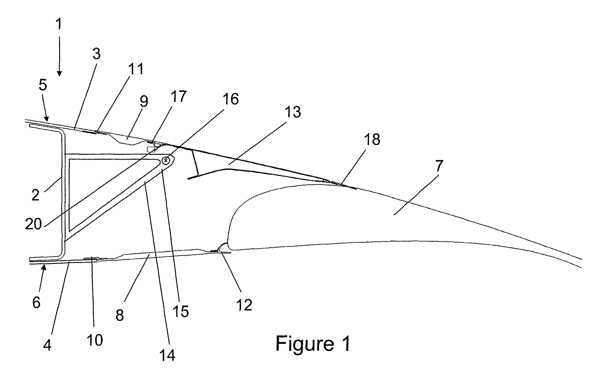
[0033]FIG. 1 shows a partial section view of an aircraft wing trailing edge. The wing includes a fixed wing portion 1 comprising a rear spar 2, an upper wing cover 3 and a lower wing cover 4. Outer surfaces of the upper and lower wing covers 3, 4 form upper and lower aerodynamic surfaces 5, 6, respectively.

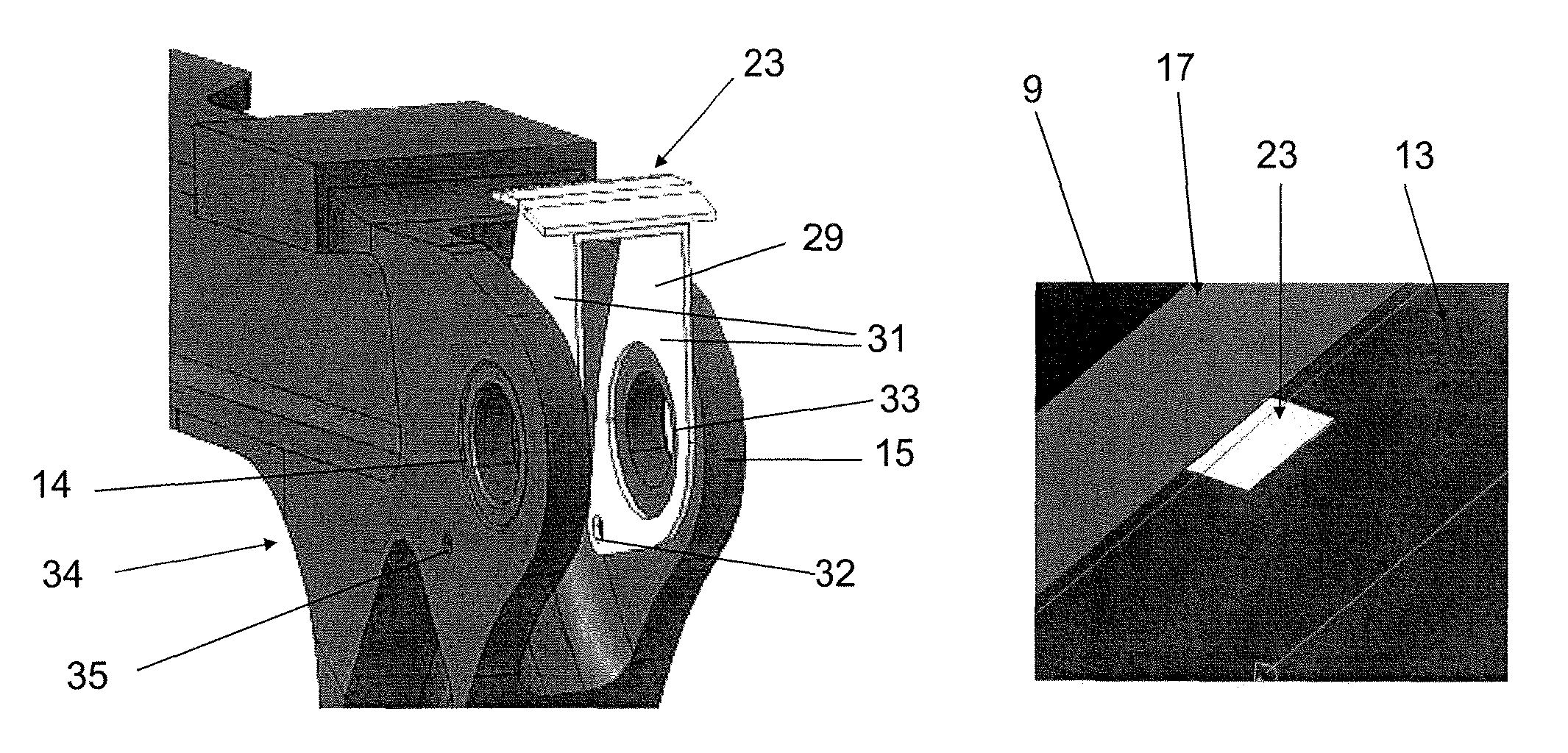
[0034]A trailing edge drop hinge flap 7 is mounted to the fixed wing portion 1 by a drop hinge mechanism (not shown). A lower trailing edge panel 8 and an upper trailing edge panel 9 complete the wing profile and provide maintenance access to the drop hinge flap mechanism. The lower trailing edge panel 8 is connected to the lower wing cover 4 by a butt-strap 10, and the upper trailing edge panel 9 is connected to the upper wing cover 3 by a butt-strap 11. A seal member 12 seals between the lower trailing edge panel 8 and the flap 7 when the flap is in its retracted (cruise) position as shown in FIG. 1.

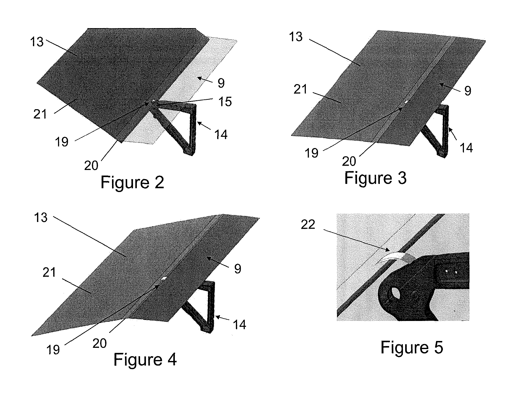
[0035]A drooping spoiler 13 is pivotally connected to the fixed wing portion 1 b...


PUM


Abstract

A panel assembly for an aircraft comprises a panel rotatably connected to a support structure and moveable between a first position and a second position. The panel has an aerodynamic surface with a slot at one edge thereof which receives a portion of the support structure when the panel is in the first position. The assembly further comprises a resilient seal member which occupies the slot when the panel is in the second position. The panel may be an aircraft flight control surface, or an aircraft landing gear bay door.

Description

RELATED APPLICATIONS[0001]The present application is based on, and claims priority from British Patent Application Number 0908751.1, filed May 21, 2009, the disclosure of which is hereby incorporated by reference herein in its entirety.FIELD OF THE INVENTION[0002]The present invention relates to sealing of a slot in an aircraft panel. In particular, the panel may be a flight control surface or a landing gear bay door.BACKGROUND OF THE INVENTION[0003]Aircraft have flight control surfaces on the leading and / or trailing edges of their aerofoil sections, such as the wings, horizontal tailplane, and vertical tailplane. Common leading or trailing edge devices are slats, flaps, spoilers, ailerons, elevators, rudders and air brakes. These flight control surfaces typically operate to provide enhanced lift or drag during low speed flight, for example take-off / climb and landing / descent, or to provide pitch, roll and yaw control during any of the flight phases.[0004]Flight control surfaces are ...

Claims


Application Information

Patent Timeline
Patent Type & Authority Patents(United States)
IPC IPC(8): B64C1/38
CPCB64C7/00B64C9/02B64C9/16B64C25/16B64C2009/143Y02T50/32Y02T50/30
Inventor BLADES, PAUL
Owner AIRBUS OPERATIONS LTD
Why Eureka
Try Eureka