Flat and thin LED-based luminary

a technology of led-based luminaires and led-based lamps, which is applied in the direction of planar/plate-like light guides, lighting and heating apparatus, instruments, etc., can solve the problems of increasing the cost of ownership, the need for a sufficiently long life of light sources, and the relative limited life of fluorescent tubes, etc., to achieve the effect of long li

Inactive Publication Date: 2013-08-20
KONINK PHILIPS ELECTRONICS NV
View PDF9 Cites 0 Cited by
  • Summary
  • Abstract
  • Description
  • Claims
  • Application Information

AI Technical Summary

Benefits of technology

[0008]It is an object of the present invention to at least partly overcome the problems of the prior art and to provide a light emitting device that has a long lifetime, is resistant to dirt and dust and is capable of emitting light of variable colors.

Problems solved by technology

Firstly, the light source should have a sufficiently long lifetime.
Conventional luminaries are often based on fluorescent tubes, which have a relatively limited lifetime.
This corresponds to a replacement every 2 years, which adds to the cost of ownership.
A luminary that collects dust will become less efficient, since the dirt blocks light.
However, as mentioned above, fluorescent tubes have a limited lifetime and are expensive to replace.
Further, the breakdown of a single fluorescent tube in this prior art luminary has a drastic negative impact on the lighting capacity of the lighting panel and on the homogeneity of the light from the lighting panel.
Further, the saw tooth shaped backside of the luminary according to the '358 patent can easily trap a lot of dust and dirt, and is rather complicated to clean.
Additionally, fluorescent tubes emit a constant spectrum, which limits the color variability capacity of such a lighting panel.

Method used


Image

  • Flat and thin LED-based luminary
  • Flat and thin LED-based luminary
  • Flat and thin LED-based luminary

Examples


Embodiment Construction

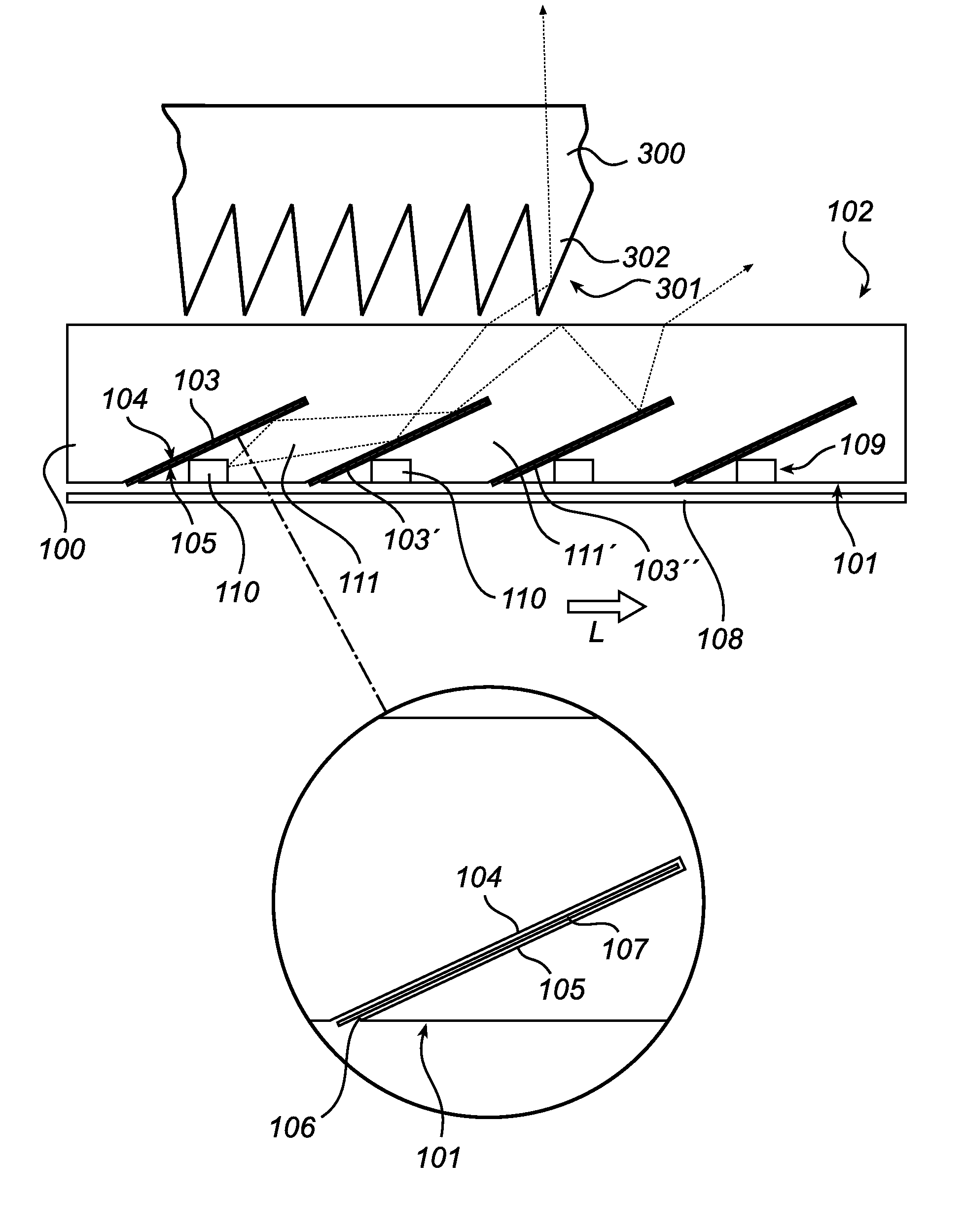
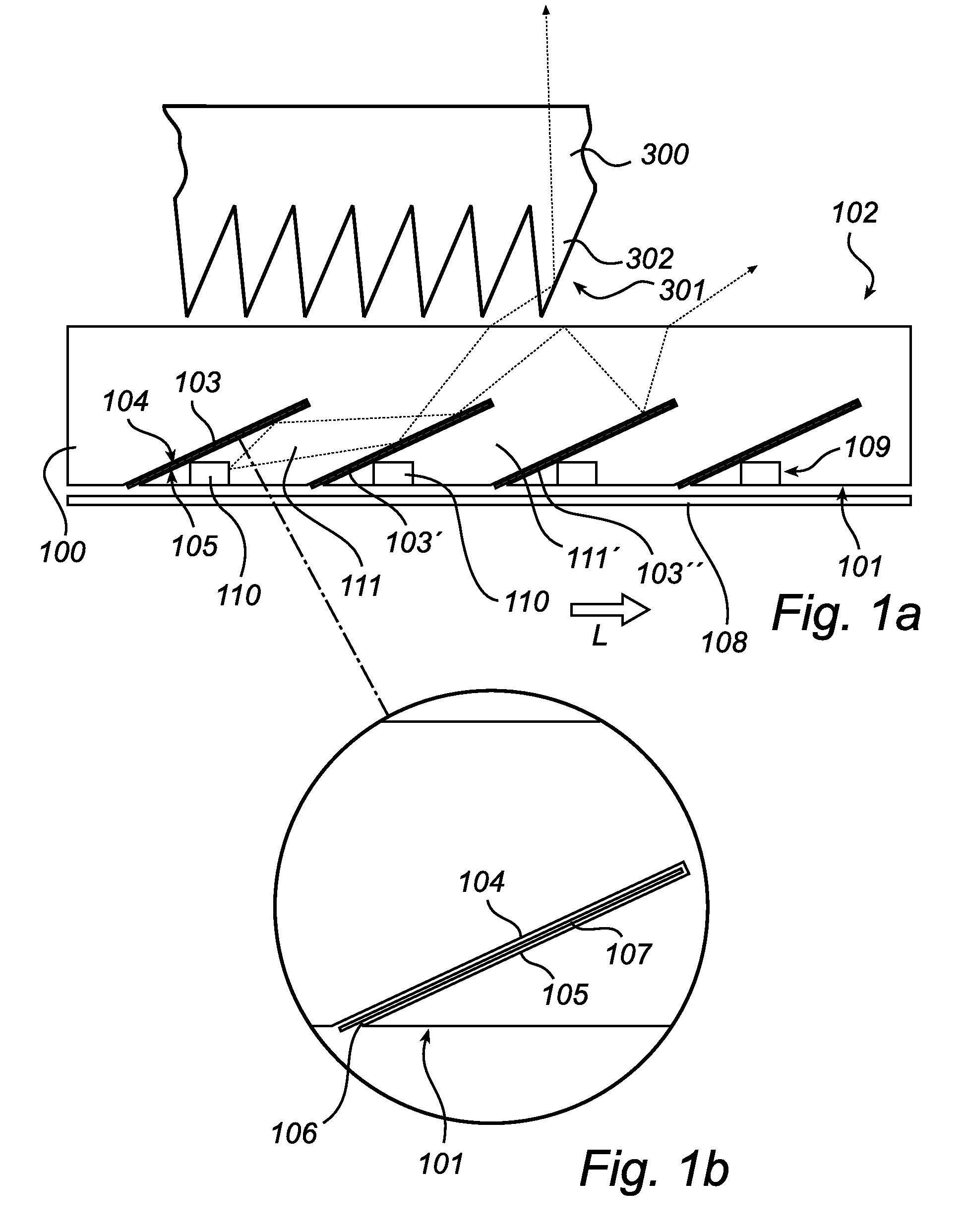
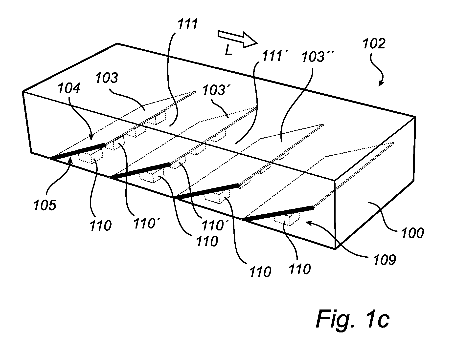
[0050]The present invention relates in one aspect to a light emitting device comprising at least a light guide plate and at least one light emitting diode arranged to emit light into the light guide plate. In another aspect, the present invention relates to such a light guide plate it self. While the below embodiments describe a light emitting device, all details regarding the light guide plate in the described light emitting device also applies to the light guide plate aspect of the invention.

[0051]An exemplary embodiment of a light emitting device of the present invention is illustrated in FIG. 1a-c and comprises a light guide plate 100 and a plurality of light emitting diodes 110.

[0052]The light guide plate 100 is at least partly transmissive, e.g. translucent or even transparent, and e.g. made of a transparent material, such as optically clear glass, ceramics or plastic material. PMMA (polymetylmethacrylate) and polycarbonate are examples of suitable plastic materials.

[0053]The ...


PUM


Abstract

A light emitting device is provided, comprising a light guide plate (100) and at least one light emitting diode (110). An array of mutually spaced apart reflective surface elements (103, 103′) is arranged between said back surface (102) and said front surface (103). The reflective surface elements (103, 103′) are non-parallel relative to said back surface (101) and front surface (102), and have a front side (104) facing said front surface (102) and a back side (105) facing said back surface (101). The back surface (105) of a reflective surface element (103) faces the front surface (104) of an adjacent reflective surface element (103′). The at least one light emitting diode (110) is arranged to emit light into a region (111) between two adjacent ones of said reflective surface elements (103, 103′). Since the reflective surface elements are located within the light guide, both the back surface and the front surface of the light guide plate may be made flat. This flat surface may easily be kept clean from dust and dirt.

Description

FIELD OF THE INVENTION[0001]The present invention relates to a light emitting device comprising at least one light emitting diode and a light guide plate. The present invention also relates to such a light guide plate it self and a luminary comprising at least one such light emitting device.BACKGROUND OF THE INVENTION[0002]Especially if applied in, for instance an office or a professional environment, luminaries should fulfill several requirements. Firstly, the light source should have a sufficiently long lifetime. Conventional luminaries are often based on fluorescent tubes, which have a relatively limited lifetime. In a typical office environment, the tubes themselves need to be replaced every 6000 hours. This corresponds to a replacement every 2 years, which adds to the cost of ownership.[0003]Secondly, the light output of the luminary should be robust against dust and other dirt. A luminary that collects dust will become less efficient, since the dirt blocks light. Since cleanin...

Claims


Application Information

Patent Timeline
Patent Type & Authority Patents(United States)
IPC IPC(8): F21V7/04
CPCG02B6/0015G02B6/0031G02F1/133603G02F1/133605G02B6/0011G02B6/0035G02B6/0021H01L33/60
Inventor VISSENBERG, MICHEL CORNELIS JOSEPHUS MARIEIJZERMAN, WILLEM LUBERTUS
Owner KONINK PHILIPS ELECTRONICS NV
Why Eureka
Try Eureka