Hand-held power tool, in particular hand-guided grinding machine

a technology of hand-held power tools and hand-guided grinding machines, which is applied in the direction of portable grinding machines, grinding machines, metal-working equipment, etc., can solve the problems of damage to the wheel guard and/or its locking device, and achieve the effect of influencing the intensity and the ratio of clamping forces

Active Publication Date: 2013-08-20
ROBERT BOSCH GMBH
View PDF20 Cites 4 Cited by
  • Summary
  • Abstract
  • Description
  • Claims
  • Application Information

AI Technical Summary

Benefits of technology

[0014]This can be achieved in a particularly simple way by means of spring means embodied in the form a torsion spring bent into a U-shape, with a locking leg and a fastening leg that are connected by means of its U-shaped vertex bend; the fastening leg is fastened to the housing and the locking leg has locking elements that engage with locking elements provided on the side of the collar of the hub and extends transversely to the axis of the drive spindle.
[0016]The torsion spring is suitably embodied in the form of a leaf spring with a flat locking leg and flat fastening leg, each oriented transversely relative to the spring plane; the legs are able to pivot relative to each other in the direction of the spring plane by means of the vertex bend, as a result of which it is possible to achieve powerful clamping forces for the locking and powerful supporting forces for the elastic support. These forces can also be influenced in their intensity and their ratio to one another by virtue of the fact that the fastening leg and the locking leg extend at an angle to each other, viewed in the direction of the spring plane, resulting in an offset of the torsion spring in the region of the vertex bend. Such an offset also has the advantage that the legs extend transversely relative to the spring plane, offset from each other by an angle so that a fastening screw that passes through the fastening leg in the vicinity of the vertex bend lies outside the overlap region of the locking leg and is thus easily accessible.

Problems solved by technology

The rotationally rigid support results in the fact that in the event of damage to the tool, e.g. when a grinding wheel bursts and as a result, wheel fragments become wedged against the wheel guard or when a tool fragment becomes wedged between the tool and wheel guard, in particular the wheel guard and / or its locking device can be damaged.

Method used


Image

  • Hand-held power tool, in particular hand-guided grinding machine
  • Hand-held power tool, in particular hand-guided grinding machine
  • Hand-held power tool, in particular hand-guided grinding machine

Examples


Embodiment Construction

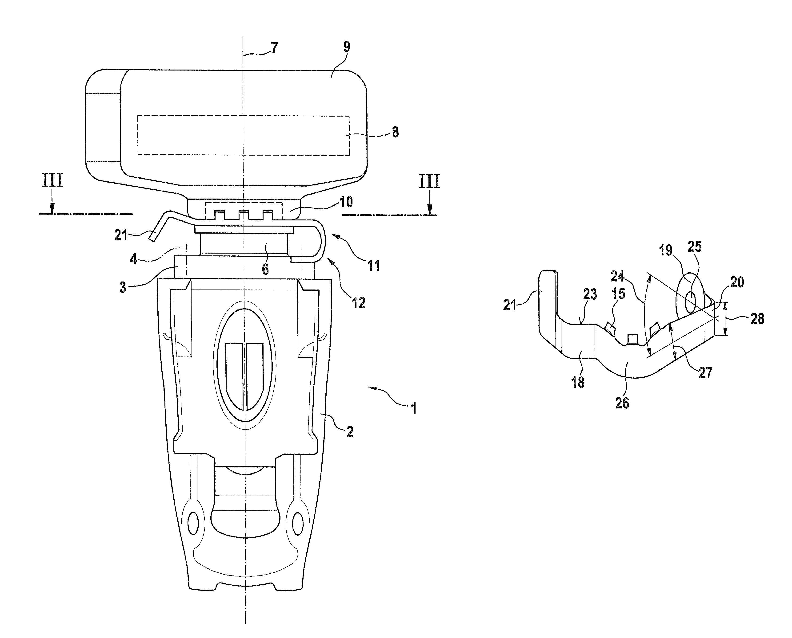
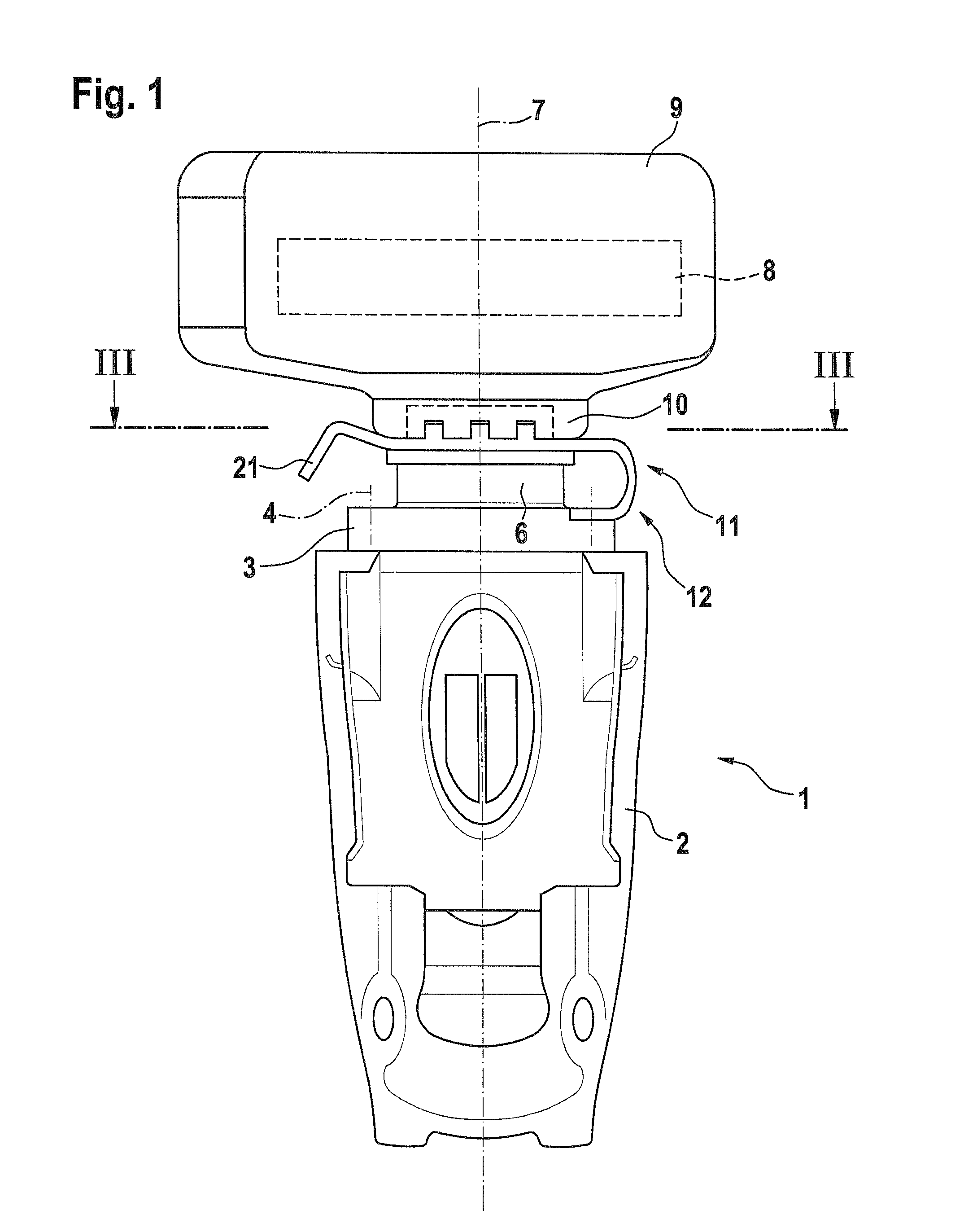
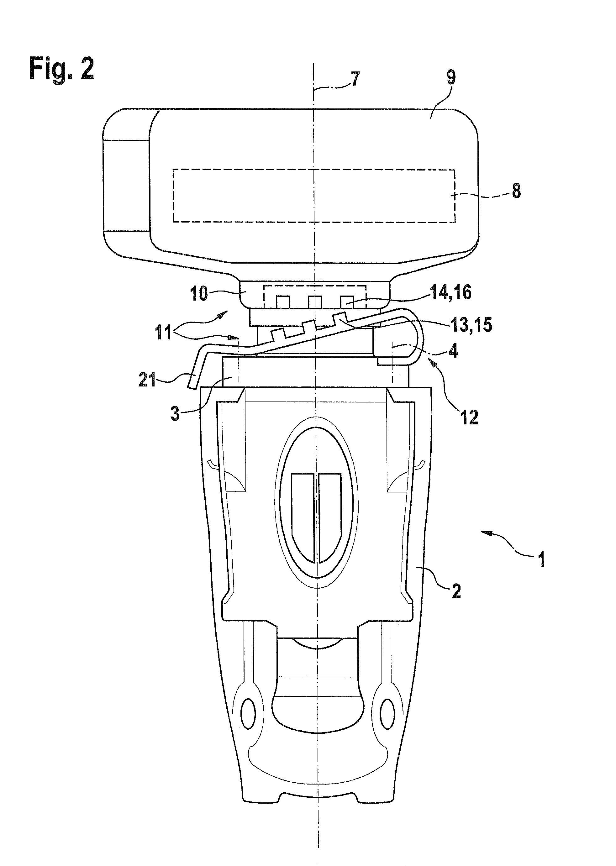
[0025]FIGS. 1 and 2 show corresponding side-view depictions of a hand-held power tool embodied in the form of a hand-guided grinding machine 1. In the exemplary embodiment, the grinder 1 is embodied in the form of an electrically driven machine and has a housing 2, which in a known fashion not depicted here, accommodates a drive unit with a motor and a subsequent transmission and in the exemplary embodiment, is connected at one of its axial ends to a bearing flange 3—by means of screws in the exemplary embodiment. These axial screw connections are labeled with the reference numeral 4 here.

[0026]As shown in FIG. 3, the bearing flange (see also FIGS. 1 and 2) has a drive spindle 5 passing through it—whose drive direction is labeled with the reference numeral 38—and transitions into a bearing journal 6. The drive spindle 5 extends at least approximately coaxial to the bearing journal 6. The rotational and longitudinal axis of the drive spindle 5 is labeled with the reference numeral 7....


PUM


Abstract

A protective guard is provided for a hand-held power tool, in particular a hand-guided grinding machine. According to the invention, the tool is at least partially covered by the protective guard. The guard is supported in an elastically flexible fashion in the circumference direction of the bearing journal by means of a spring means that prestress locking elements of a locking mechanism in their engaged positions.

Description

CROSS-REFERENCE TO RELATED APPLICATION[0001]This application is a 35 USC 371 application of PCT / EP2008 / 065379 filed on Nov. 12, 2008.BACKGROUND OF THE INVENTION[0002]1. Field of the Invention[0003]The invention relates to a hand-held power tool, in particular a hand-guided grinding machine, preferably a grinding machine embodied in the form of an angle grinder.[0004]2. Description of the Prior Art[0005]In a hand-held power tool known from EP 0 583 270 B1, which is embodied in the form of a hand-guided angle grinder, a wheel guard is provided for the tool, which is supported on a drive spindle; the wheel guard is supported by means of a hub part on the bearing journal of the housing bearing flange of the drive spindle and is embodied to be immobilized in a rotationally rigid fashion in a plurality of rotation positions by means of a locking device.[0006]The hub part is embodied in the form of a hat-shaped sheet metal cap that is slid axially onto the bearing journal and axially immob...

Claims


Application Information

Patent Timeline
Patent Type & Authority Patents(United States)
IPC IPC(8): B24B55/05
CPCB24B23/02B24B55/052
Inventor NAGY, ATTILA
Owner ROBERT BOSCH GMBH
Why Eureka
Try Eureka