
Card flat removal device

Inactive Publication Date: 2013-08-27
MASCHINENFABRIK RIETER AG
View PDF17 Cites 0 Cited by
  • Summary
  • Abstract
  • Description
  • Claims
  • Application Information

AI Technical Summary

Benefits of technology

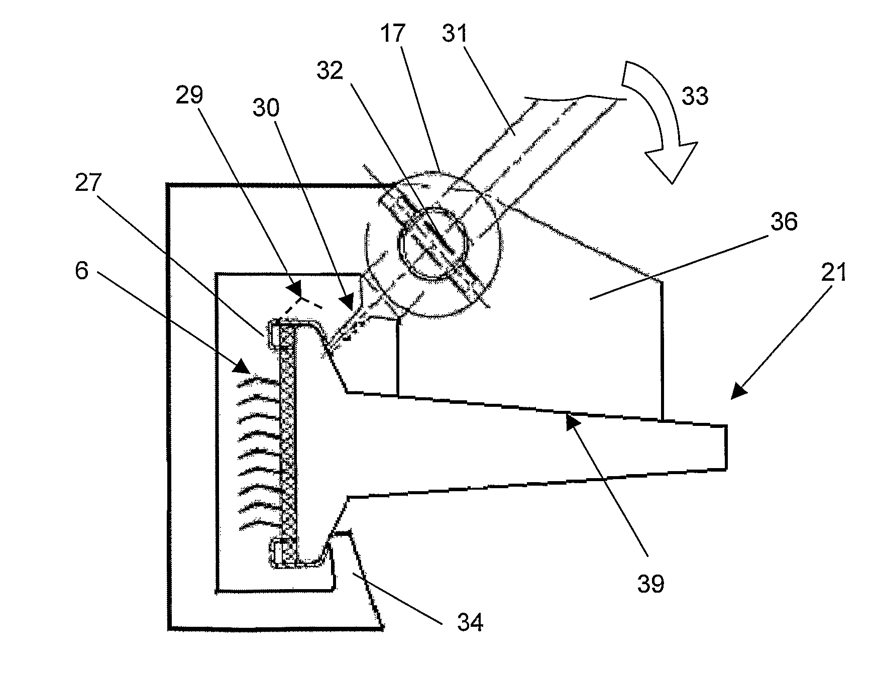
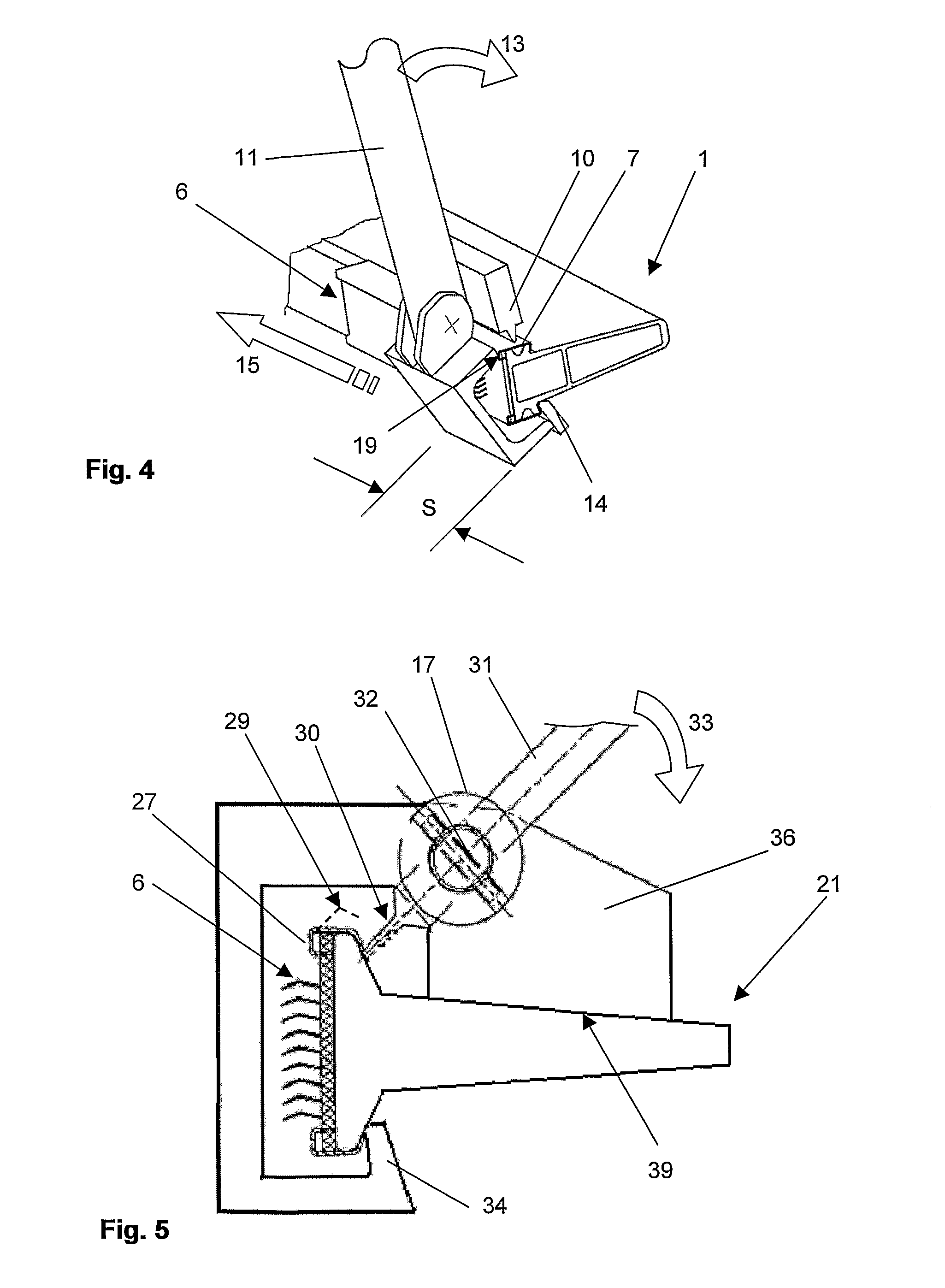
The invention aims to simplify the process of removing clothes clips from card-flat bars without causing any damage to the bar. The device is designed to be easily placed on the bar and can be moved around to different segments without needing to be removed and redone. This saves time and effort and ensures the quality of the card-flat bar is not compromised. The device is designed to be opened and closed over a segment, allowing for easy removal of the clips and clothes strip without affecting the bearing face of the foot. The device can be used either automatically or manually.

Problems solved by technology

Since the necessary forces for peeling out the clothing strip are high, when knives of this type are used manually, there is a high probability of the card-flat bar being damaged, whether by the card-flat bar being twisted or by the bearing face on the card-flat foot being impaired.
The disadvantage remains, however, that the bearing face on the card-flat foot is damaged by the knife.

Method used


Image

  • Card flat removal device
  • Card flat removal device
  • Card flat removal device

Examples


Embodiment Construction

[0025]Reference will now be made to embodiments of the invention, one or more examples of which are shown in the drawings. Each embodiment is provided by way of explanation of the invention, and not as a limitation of the invention. For example features illustrated or described as part of one embodiment can be combined with another embodiment to yield still another embodiment. It is intended that the present invention include these and other modifications and variations to the embodiments described herein.

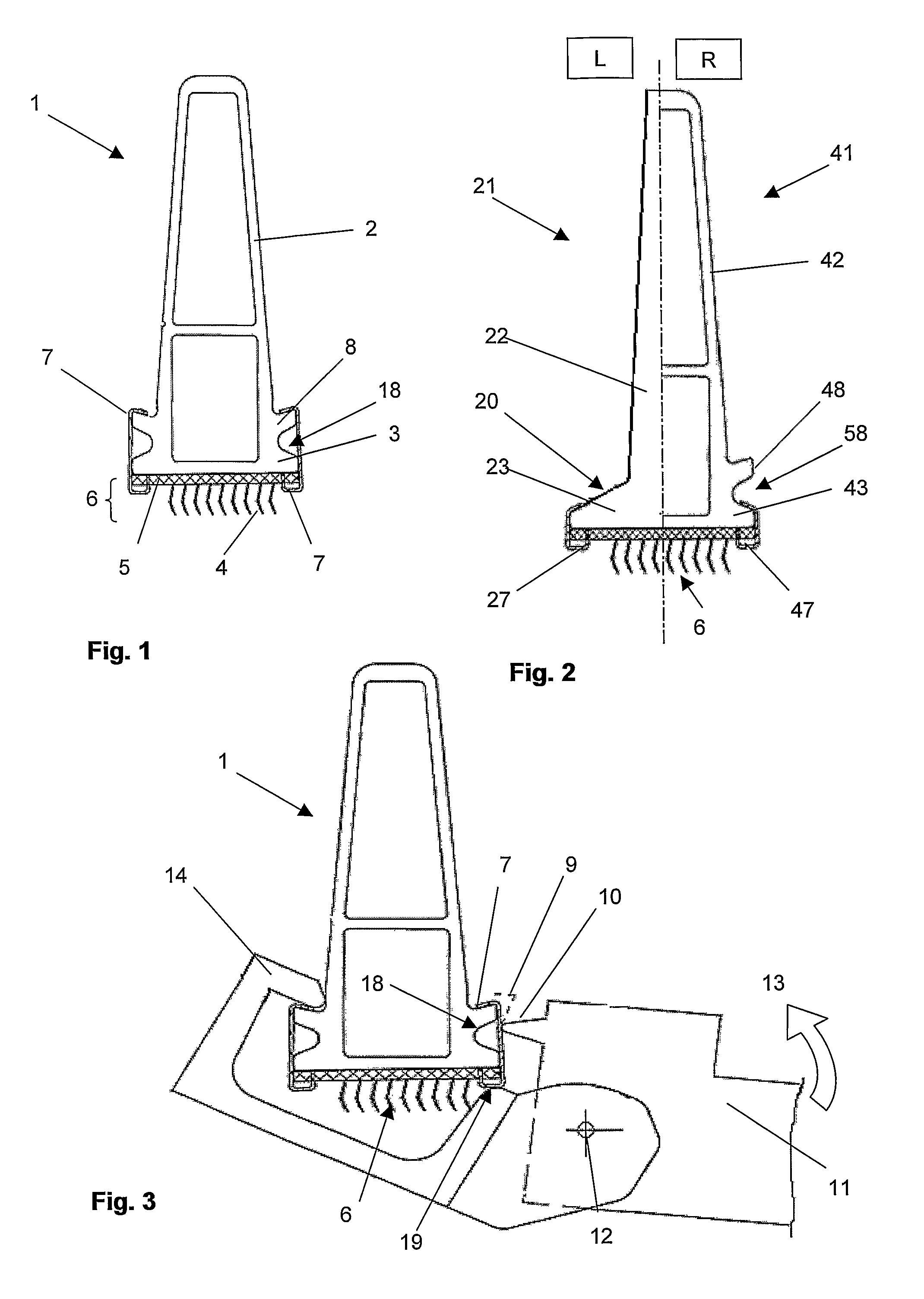
[0026]FIGS. 1 and 2 show diagrammatic illustrations of cross sections of various forms of construction of card-flat bars and are to serve for explaining possible types of construction and fastenings of clothing strips on card-flat bars.

[0027]FIG. 1 shows a card-flat bar 1 which has been manufactured as a hollow profile. The card-flat bar 1 comprises a card-flat foot 3 and a web 2. A rib 8 is integrally formed on the web 2 on both sides of the latter. The rib 8 runs over the entire ...


PUM

PropertyMeasurementUnit
Lengthaaaaaaaaaa
Shapeaaaaaaaaaa

Abstract

A method and a device for drawing off a clothing strip from a card-flat bar are presented. A clothing strip held on the card-flat bar by fastening means in the form of clips or clamps is released form the card-flat bar with the aid of a device resulting in at least partial opening of the fastening means. The device has a bearing face and a retainer for bearing on the card-flat bar or on the clip and has a spike for the at least partial opening of the clip.

Description

FIELD OF THE INVENTION[0001]The invention relates to a device and a method for drawing off a clothing strip from a card-flat bar.BACKGROUND OF THE INVENTION[0002]Various types of construction of card-flat bars and various methods for fastening clothing strips to these card-flat bars are known from the prior art. The card-flat bars used currently on cards as revolving card flats are preferably equipped with flexible clothings. These clothings have a base or foundation built up from a plurality of fabric layers. The base holds small wire hooks which form the actual clothing elements. The clothings are manufactured in the form of strips. The strips correspond in length and width to the card-flat bars. These clothing strips are usually fastened to both longitudinal sides of the card-flat bar by fastening means in the form of clips or clamps. The clothing strip in this case lies on the underside of the card-flat foot. This bearing face of the card-flat foot has to satisfy high quality re...

Claims


Application Information

Patent Timeline
IPC IPC(8): B23P19/04D01G15/12D01G15/92
CPCD01G15/24D01G15/92Y10T29/53896Y10T29/53683
Inventor SCHATZMANN, HANS-PETER
Owner MASCHINENFABRIK RIETER AG
Learn More