
Solid state resistance welding for airfoil repair and manufacture

a solid-state resistance welding and airfoil technology, which is applied in the direction of manufacturing tools, forging/pressing/hammering equipment, turbines, etc., can solve the problems of increasing repair costs, time-consuming and expensive process of replacing a portion deteriorating edges of the blade and/or the tip of the compressor blade airfoil, etc., to reduce or eliminate offsets

Active Publication Date: 2013-08-27
GENERAL ELECTRIC CO
View PDF19 Cites 3 Cited by
  • Summary
  • Abstract
  • Description
  • Claims
  • Application Information

AI Technical Summary

Benefits of technology

The patent describes a method to create an airfoil with twist by coining the parts that make up the upper and stub airfoil sections. This helps to decrease or eliminate the gap between the leading and trailing edges of these sections. The coining process involves using tools to press the parts between coining dies. The technical effect of this method is that it improves the quality and efficiency of airfoil manufacturing.

Problems solved by technology

During engine operation, leading and trailing edges of the blade and / or a tip of the compressor blade airfoil may deteriorate or become damaged due to any of a number of distress modes, including, but not limited to, foreign object damage (FOD), tip rubbing, oxidation, thermal fatigue cracking, or erosion caused by abrasives and corrosives in the flowing gas stream.
Thus, replacing a portion of a compressor blade airfoil may be a time-consuming and expensive process.
Additionally, more complex airfoil shapes, for example three-dimensional aerodynamic configurations may increase the difficulty of welding and blending the repaired airfoil, thus resulting in increased repair costs.

Method used


Image

  • Solid state resistance welding for airfoil repair and manufacture
  • Solid state resistance welding for airfoil repair and manufacture
  • Solid state resistance welding for airfoil repair and manufacture

Examples


Embodiment Construction

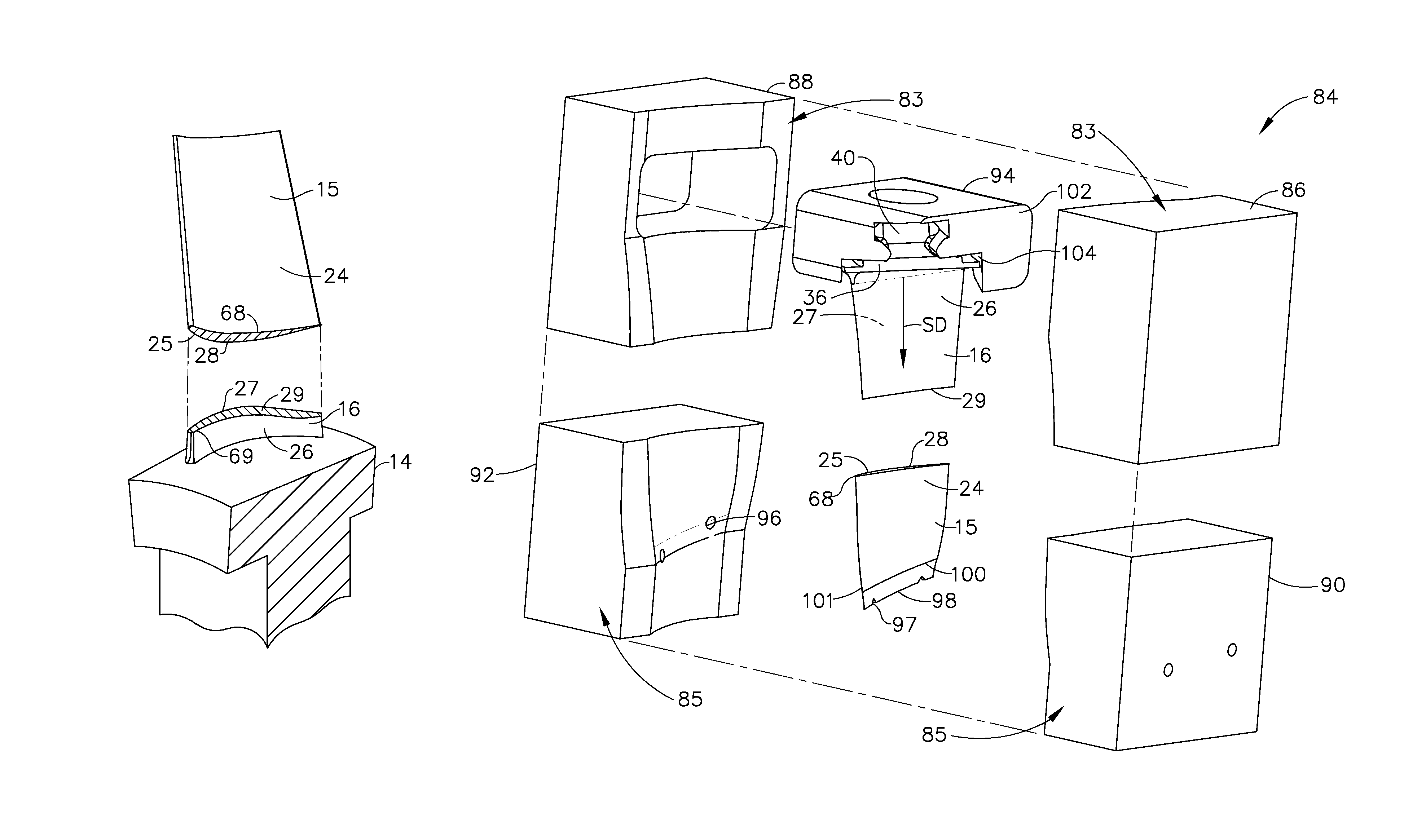
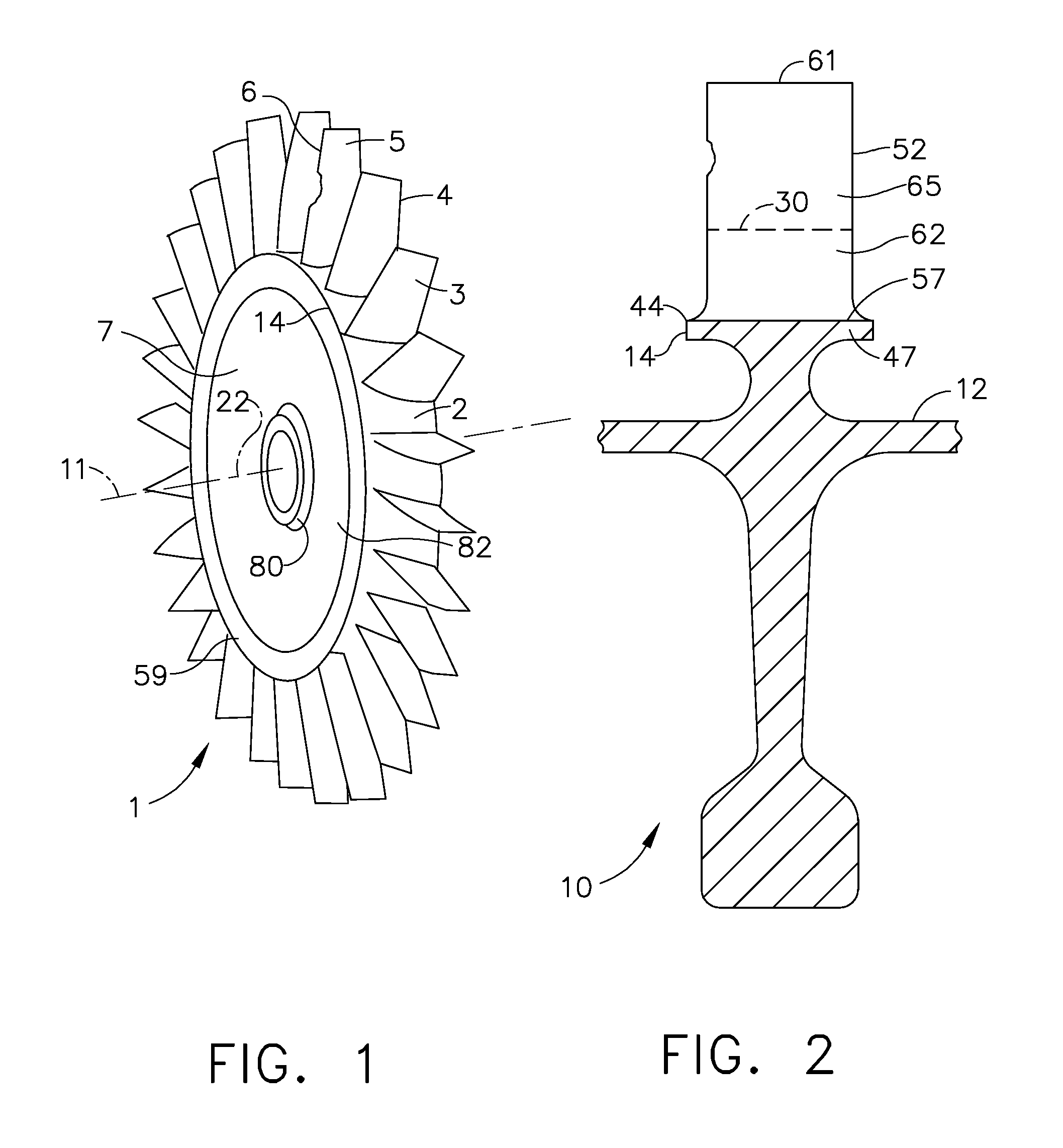
[0037]Illustrated in FIG. 1 is an exemplary turbofan gas turbine engine BLISK 1 circumscribed about an engine centerline 11 and having a plurality of airfoils 3 extending radially outwardly from a peripheral surface 2 of an annular rim 59 of a disk 7 of the BLISK 1. The airfoils 3 integral with the disk 7 and are illustrated as including undamaged airfoils 4 and a damaged airfoil 5 which is damaged in the area of its leading edge 6. The BLISK 1 includes a hub 80, a web 82 extending radially outwardly from the hub to the annular rim 59 and is circumscribed around an axis 22 which coincides with the engine centerline 11.

[0038]Illustrated in FIG. 2 is an exemplary portion of a turbofan gas turbine engine BLUM 10 which may be from a fan or compressor of the engine. BLISKS have blades or airfoils that are integral with a disk and BLUMS have blades or airfoils that are integral with a drum 12. A plurality of airfoils 52 extend radially outwardly from, are circumferentially disposed about,...


PUM

PropertyMeasurementUnit
lengthaaaaaaaaaa
pressureaaaaaaaaaa
airfoil pressureaaaaaaaaaa

Abstract

A method for bonding airfoil sections includes aligning upper and stub airfoil sections having upper airfoil pressure and suction sides and stub airfoil pressure and suction sides respectively, pressing together upper and stub airfoil cross sections at upper and stub airfoil distal ends of the upper and stub airfoil sections respectively, and then resistance welding, preferably solid state resistance welding, the upper and stub airfoil sections together along the upper and stub airfoil cross sections by passing electrical current across the upper and stub airfoil cross sections. The upper and stub airfoil sections may be clamped between pressure and suction side upper airfoil electrodes and between the stub airfoil pressure and suction sides respectively. The method may be performed while the stub airfoil section is attached to an airfoil carrier such as a rotor disk rim, a gas turbine engine drum, or a gas turbine engine blade platform.

Description

CROSS-REFERENCE TO RELATED APPLICATIONS[0001]This application is a Continuation-In-Part of application Ser. No. 10 / 713,493, filed Nov. 14, 2003.BACKGROUND OF THE INVENTION[0002]1. Field of the Invention[0003]This application relates generally to gas turbine engine blades and, more particularly, to methods for welding airfoil sections of gas turbine engine rotor blades.[0004]2. Description of Related Art[0005]At least some known gas turbine engines include a compressor for compressing air which is mixed with a fuel and channeled to a combustor wherein the mixture is ignited within a combustion chamber for generating hot combustion gases. The hot combustion gases are channeled downstream to a turbine, which extracts energy from the combustion gases for powering the compressor, as well as producing useful work to propel an aircraft in flight or to power a load, such as an electrical generator.[0006]Known compressors include a rotor assembly that includes at least one row of circumferen...

Claims


Application Information

Patent Timeline
Patent Type & Authority Patents(United States)
IPC IPC(8): B23P6/00B23K9/28B23K11/00
CPCB23P6/005B23K11/04F01D5/005B23K11/002B23K11/3081Y10T29/4973Y10T29/49336Y02T50/671Y10T29/49737Y02T50/673Y10T29/4932F05D2230/232Y10T29/49318B23K2201/001B23K2101/001Y02T50/60
Inventor TREWILER, GARY EDWARDFERRIGNO, STEPHEN JOSEPHWILKINS, MELVIN HOWARDTRAPP, TIMOTHY JOSEPHSTEWART, MATTHEWFIRESTONE, GREGORY CHRISTOPHER
Owner GENERAL ELECTRIC CO
Features
  • Generate Ideas
  • Intellectual Property
  • Life Sciences
  • Materials
  • Tech Scout
  • Unparalleled Data Quality
  • Higher Quality Content
  • 60% Fewer Hallucinations
Learn More