Method for displaying a hollow space in an object under investigation

a technology of hollow space and object, applied in the field of hollow space, can solve the problems of not providing medical staff with a rapid means of guidance, and it is difficult for neuroradiologists to reconcile the captured two-dimensional projection data sets with the complex, so as to improve the guidance

Active Publication Date: 2013-08-27
SIEMENS HEALTHCARE GMBH
View PDF10 Cites 45 Cited by
  • Summary
  • Abstract
  • Description
  • Claims
  • Application Information

AI Technical Summary

Benefits of technology

[0007]The object of the invention is to provide a method of the type described in the introduction, providing the medical staff with improved guidance in the object being examined.
[0008]This object is achieved by an inventive method of the type described in the introduction, in that the access point and / or the target point is highlighted in the spatial display of the hollow space section. Highlighting of the access point and / or target point in the spatial display of the hollow space section is carried out as a rule by the medical staff. Not only the target point to be reached by the surgical instrument but also in appropriate cases the access point are highlighted in the spatial display. Highlighting the access point and target point proves to be advantageous when the medical staff need to be sure of their direction in a hollow space taking the form of a blood vessel system with a high degree of branching—such as a coronary or intracranial vascular tree. Highlighting makes the course of the blood vessel from the access point to the target point easier to recognize among a high number of branches and further blood vessels. For this it is not necessarily obligatory for a surgical instrument to be introduced into the hollow space section. However the method can be used during a surgical operation and for planning an operation.

Problems solved by technology

In so doing it often proves difficult for the neuroradiologist to reconcile the captured two dimensional projection data sets with the complex, three dimensional shape of the actual vascular tree.
The disadvantage of this method is that it does not provide the medical staff with a rapid means of guidance within the vascular tree recording.

Method used


Image

  • Method for displaying a hollow space in an object under investigation
  • Method for displaying a hollow space in an object under investigation

Examples


Embodiment Construction

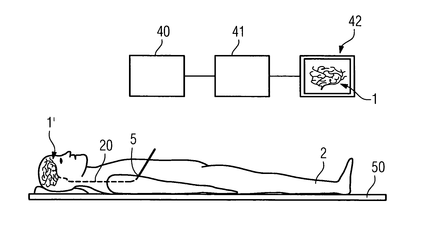
[0023]FIG. 1 shows a device for determining the spatial display 1 of a hollow space in the form of a hollow organ 1′ in a human body 2. In the exemplary embodiment, the hollow organ 1′ of which a spatial display is to be determined takes the form of an intracranial vascular tree 1′. Data concerning the body 2 is captured by means of a recording unit 40 in order to determine a spatial display 1 of the intracranial vascular tree 1′. For this purpose the human body 2 is arranged on a couch 50. The recording unit 40 can be produced in numerous forms, such as a magnetic resonance device or a tomography-enabled C-arm.

[0024]When the recording unit 40 has captured the data, said data is available either as a three dimensional image data set, as in magnetic resonance methods, or is converted by suitable methods, such as back projection in the case of projection data sets recorded with X-rays, into a three dimensional image data set. For this purpose the data is passed to a data processing un...


PUM


Abstract

The invention relates to a method for displaying a hollow space in an object under investigation, wherein the hollow space has an access point and a target point for a surgical instrument which can be introduced at least partially into the hollow space, and wherein a three dimensional image data set of a section of the hollow space having the access point and / or the target point is determined and spatially displayed. By highlighting the access point and / or the target point in the spatial display of the hollow space section it is possible to make a method available which provides the surgical staff with improved guidance in the object under investigation.

Description

CROSS REFERENCE TO RELATED APPLICATIONS[0001]This application claims priority of German application No. 10 2006 001 884.2 filed Jan. 13, 2006, which is incorporated by reference herein in its entirety.FIELD OF THE INVENTION[0002]The invention relates to a hollow space wherein the hollow space has an access point and a target point for a surgical instrument which can be introduced at least partially into the hollow space, and wherein a three dimensional image data set of a section of the hollow space having the access point and / or the target point is determined and spatially displayed.BACKGROUND OF THE INVENTION[0003]Hollow spaces in an object under investigation, for example vascular pathologies, in particular intracranial vascular pathologies, are frequently dealt with by means of a catheter introduced into the femoral artery and fed via the blood vessels to the site of the lesion. As a rule the positioning and / or location of the catheter is performed using continuously pulsed X-ra...

Claims


Application Information

Patent Timeline
Patent Type & Authority Patents(United States)
IPC IPC(8): A61B5/05
CPCA61B5/06A61B5/415A61B6/12A61B19/52A61B19/50A61B90/36A61B34/10A61B5/062
Inventor DIEZ, MICHAEL
Owner SIEMENS HEALTHCARE GMBH
Why Eureka
Try Eureka