Walk-behind lawnmower having a rear shield

a technology of rear shield and lawnmower, which is applied in the field of walk-behind lawnmowers, can solve the problems of reduced flexibility of rear shield, particularly severe rear shield bending, and disadvantageous rear shield bending rigidity

Active Publication Date: 2013-09-03
HONDA MOTOR CO LTD
View PDF33 Cites 7 Cited by
  • Summary
  • Abstract
  • Description
  • Claims
  • Application Information

AI Technical Summary

Benefits of technology

[0006]It is an object of the present invention to provide technology for allowing a rear shield of a walk-behind lawnmower to be prevented from becoming caught on other members of the lawnmower.
[0009]The bending part of the rear shield is thus limited to the specified site that is set in advance, and therefore the rear shield that is bent in the front and back direction can be restricted from catching on other structural components (the housing, axles, and the like) of the walk-behind lawnmower. The simple configuration requires merely that the thin-walled part be formed at the central site in the heightwise direction of the rear shield. The bending rigidity of the rear shield need not be increased in order to minimize bending of the rear shield.
[0010]Preferably, the lower end part of the sheet is formed as a round part having a circular cross-section. The lower end part is therefore not readily caught on the lawn or the grass when the lawnmower is moved forward and backward. Resistance to the movement of the lawnmower can therefore be reduced. The lower end part is also not readily caught up in the housing while the lawnmower is moving.
[0011]Desirably, the sheet comprises a protruding part projecting from the thin-walled part toward the operating handle. The lower end part may be lifted up and positioned within the housing (e.g., may be caught on the various members within the housing) when the lower half of the rear shield is bent up from the thin-walled part. The protruding part approaches nearest the lawn and is therefore readily caught on the grass, small stones, or other objects exposed on the lawn. When the lawnmower is moved forward and backward, the protruding part catches on the grass or other exposed objects; i.e., “catching” may occur. “Catching” tends to cause the protruding part to stop when the lawnmower is moving forward and backward. The lower end part that has been lifted up is pushed back by the stopping of the protruding part, and falls to the lawn. In other words, “catching” serves as a chance to knock down the lower end part that has been lifted up. A simple structure involving merely providing the protruding part thus allows the lower end part that is lifted up and positioned within the housing to be readily returned to the ground.
[0012]In a preferred form, the round part projects farther toward the operating handle than a distal end of the protruding part. The protruding part is therefore not readily caught on the grass or other exposed objects; i.e., is not readily prone to “catching” when the rear shield is moving in the forward and backward direction in response to the forward and backward motion of the lawnmower. Resistance to the motion of the lawnmower can therefore be minimized.
[0013]Preferably, the upper end part of the sheet is formed integrally with a supported part swingably supported on the rear end part of the housing; and the sheet has a rib extending from the supported part in a direction opposite the lower end part of the sheet. The rib therefore swings to the rear and contacts the housing when the rear shield swings forward. As a result, the amount of forward swinging of the rear shield is restricted. When the lawnmower is, e.g., moving in reverse, the rear shield swings forward, whereby the lower half bends up at the thin-walled part, and the lower end part may be thereby lifted up and positioned within the housing. In other words, the rear shield is caught up into the housing. The rib swings backward and contacts the housing in such instances. The amount of forward swinging of the rear shield is restricted. Contact of the lower end part of the bent rear shield with the various members positioned within the housing can therefore be minimized to the greatest possible extent.

Problems solved by technology

Bending of the rear shield is particularly severe when the height of the housing above the ground is adjusted to a minimum.
However, in such cases the flexibility of the rear shield decreases, and resistance to movement increases when changing the direction of the walk-behind lawnmower, so such an approach is inadvisable.
A rear shield having increased bending rigidity is also disadvantageous from the perspective of increasing durability to wear and breakage.
Providing a separate minimizing member for minimizing bending of the rear shield involves increasing the number of components, so such an approach is also inadvisable.

Method used


Image

  • Walk-behind lawnmower having a rear shield
  • Walk-behind lawnmower having a rear shield
  • Walk-behind lawnmower having a rear shield

Examples


embodiment 1

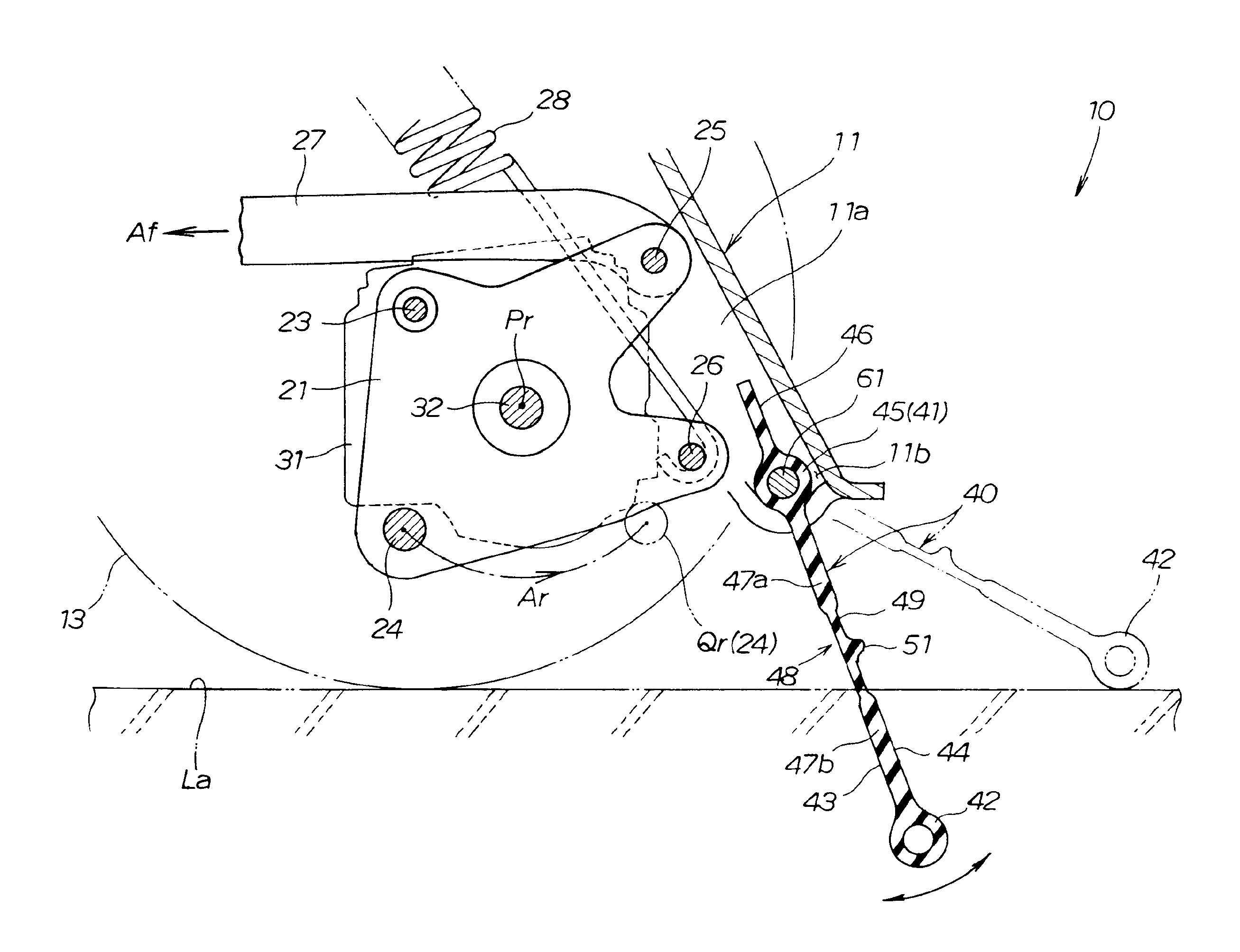
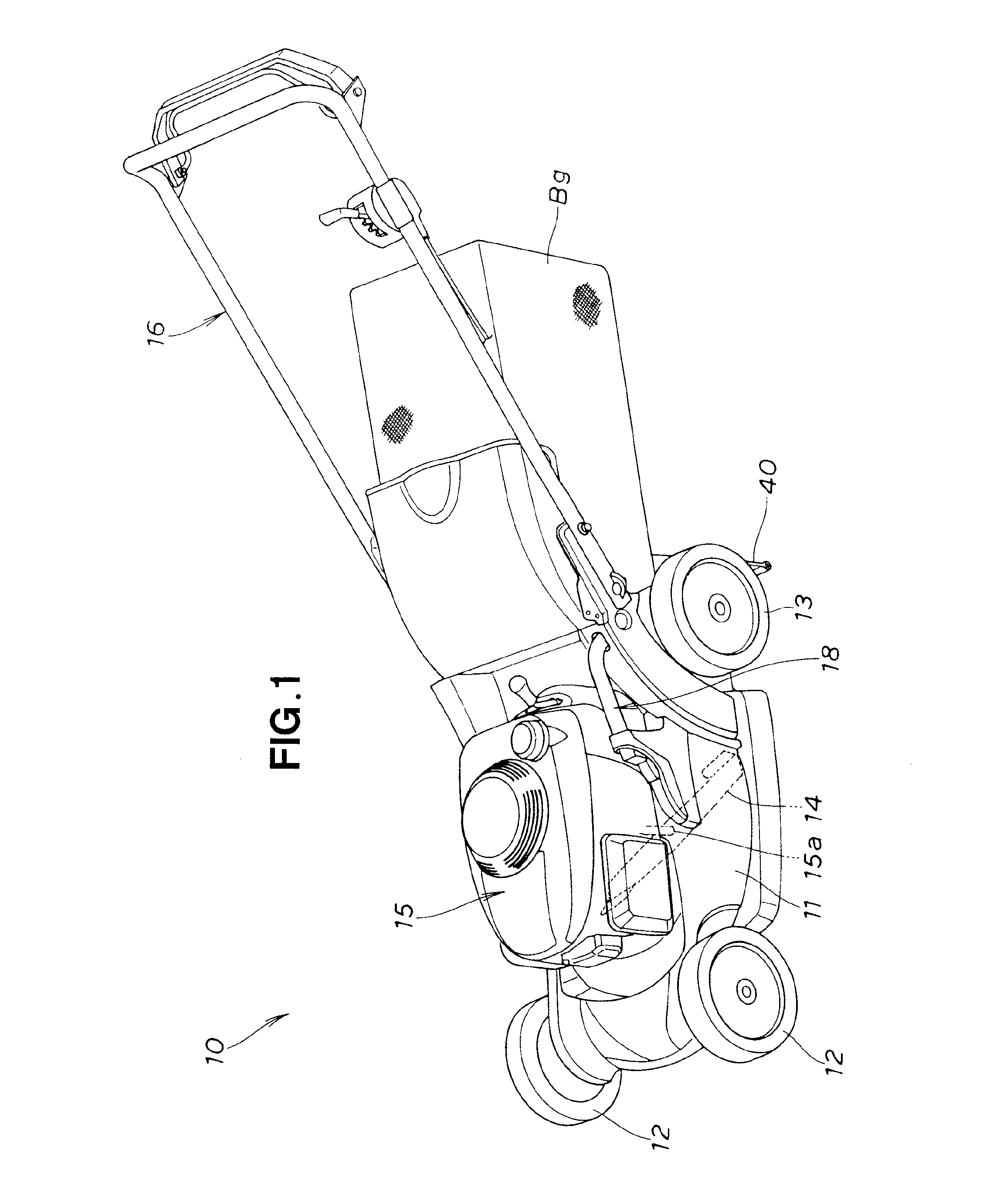
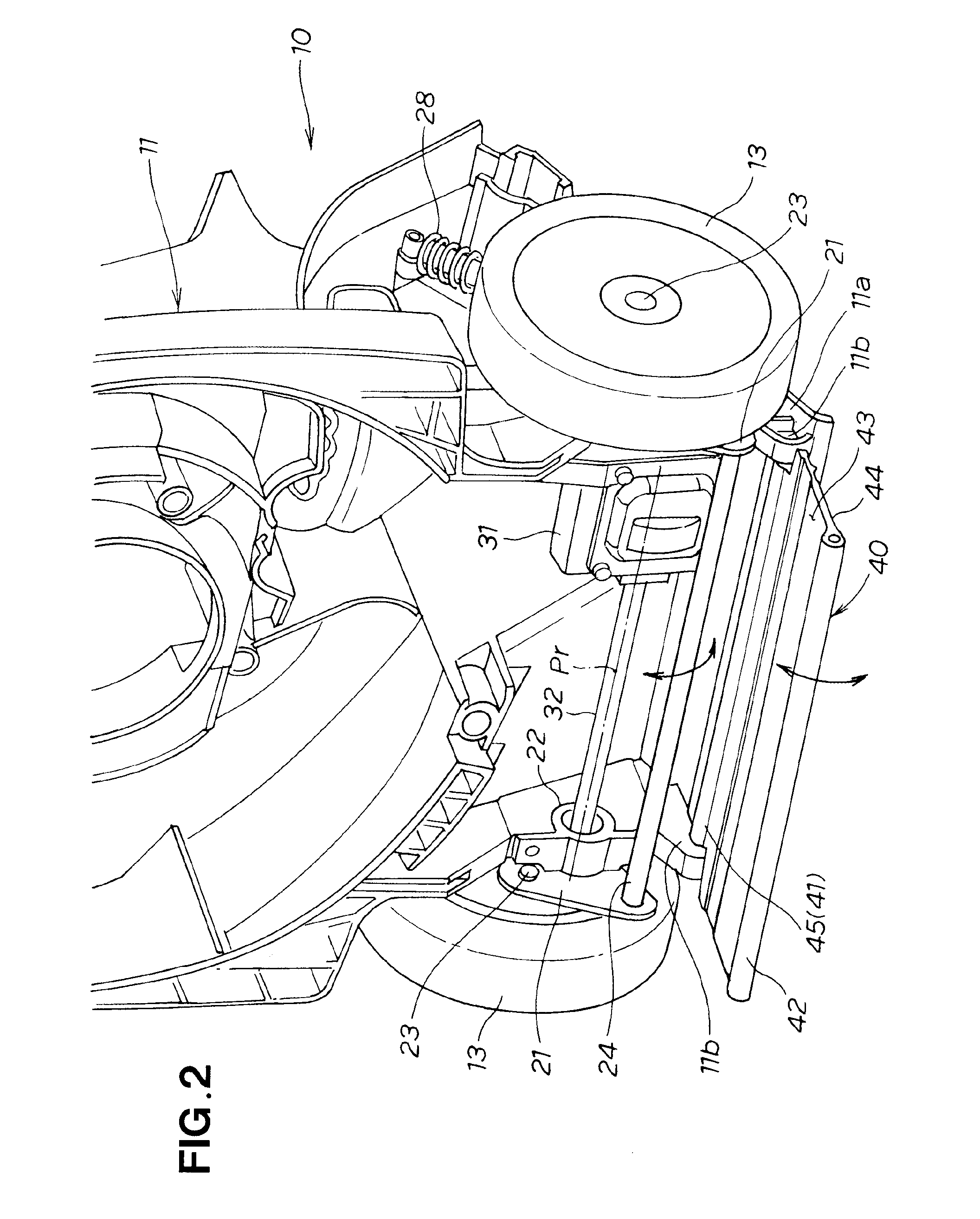
[0023]As shown in FIG. 1, a walk-behind lawnmower 10 is a walk-behind self-propelled work machine for cutting grass, and is composed of a housing 11 that is open at the bottom; left and right front wheels 12, 12 that are provided to the front part of the housing 11; left and right rear wheels 13, 13 that are provided to the rear part of the housing 11; a mowing blade 14 housed in the central interior part of the housing 11; an engine 15 provided to the upper part of the housing 11; an operating handle 16 extending to the rear from the rear part of the housing 11; and a height-adjusting grip 18 provided to the upper-left part of the housing 11.

[0024]The housing 11 is composed of, e.g., a resin-molded article and also serves as a chassis. The engine 15 is laid over and bolted to the upper surface of the housing and thereby integrally assembled therewith. The engine 15 is a so-called vertical engine that has an output shaft 15a extending from a lower end of the engine into the housing ...

embodiment 2

[0059]FIGS. 8A through 8C show the cross-sectional structures of rear shields 40A through 40C according to Embodiment 2. Embodiment 2 provides examples in which the lower end part 42 of the rear shield 40 shown in FIG. 4 has been modified. The rest of the configuration and the operation are identical to the configuration and operation of the lawnmower 10 according Embodiment 1 shown in FIGS. 1 through 7, and descriptions thereof will therefore be omitted.

[0060]Specifically, a lower end part 42A of the rear shield 40A shown in FIG. 8A does not have a through-hole; i.e., is formed as a round part having a solid circular cross-section. The lower end part 42A (round part 42A) has a perfectly circular cross-section.

[0061]A lower end part 42B of the rear shield 40B shown in FIG. 8B is formed as a round part that has an elliptical cross-section that lengthens in the direction toward the upper end part 41 when viewed in cross-section. The lower end part 42B (round part 42B) is formed in a h...


PUM


Abstract

The rear shield of a walk-behind lawnmower extends downward from a rear end part of a housing and is in the form of an elastic sheet. The sheet has a thin-walled part formed in a central site in a heightwise direction between an upper end part and a lower end part, the upper end part being attached to the rear end part of the housing. The thin-walled part has a thickness set to be smaller than a thickness of other parts.

Description

FILED OF THE INVENTION[0001]The present invention relates to a walk-behind lawnmower and, in particular, relates to a walk-behind lawnmower having an improved rear shield provided to a rear part of a housing of the lawnmower.BACKGROUND OF THE INVENTION[0002]Walk-behind lawnmowers are appropriate for cutting grass in household yards or other narrow areas, and have an operating handle extending to the rear from a housing in which a blade is housed. An example of this type of walk-behind lawnmower is disclosed in Japanese Patent Application Laid-Open Publication No. S64-37217 A.[0003]The walk-behind lawnmower disclosed in JP S64-37217 A has a housing in which the blade is rotatably housed, an operating handle that extends to the rear from the housing, and a rear shield that extends downward from the rear end part of the housing. During mowing operations using the walk-behind lawnmower, various types of debris, e.g., small rocks launched by the blade or the grass cut by the blade, may b...

Claims


Application Information

Patent Timeline
Patent Type & Authority Patents(United States)
IPC IPC(8): A01D34/00
CPCA01D34/828A01D34/84A01D34/68A01D34/82A01D2101/00
Inventor HIROSE, NOBUYUKIHOJO, HIROSHIMARUYAMA, SHUHEIMINAMI, FUMIO
Owner HONDA MOTOR CO LTD
Why Eureka
Try Eureka