Wall mountable accessory assembly

a wall mountable and accessory technology, applied in the direction of scaffold accessories, washstands, lighting support devices, etc., can solve the problems of requiring complex mounting assemblies for heavy metal structures, and affecting the overall assembly

Active Publication Date: 2013-09-03
KOHLER CO
View PDF22 Cites 16 Cited by
  • Summary
  • Abstract
  • Description
  • Claims
  • Application Information

AI Technical Summary

Benefits of technology

[0009]According to one aspect of the invention, there is provided a wall mountable accessory assembly. It has at least one bracket having a rearward portion mountable to the wall and a frontal portion having a first recess which is forwardly open, the bracket also having a side catch groove structure. The wall mountable accessory also has a projection which has been laterally slid into the catch groove structure and interfit therewith. There is also a screw inserted in the first recess so as to thereby drive a portion of the wall mountable accessory forward and thereby inhibit relative movement between the wall mountable accessory and the bracket.
[0015]However, by loosening the set screw the accessory can be removed from the bracket by reversing the lateral movement, or in compact situations (and with sufficient force) by forward movement away from the bracket.
[0016]This facilitates rough linking of the brackets and the grab bar (or the like) with respect to one another before the brackets are attached to the wall. This permits some lateral play between the components during positioning on the wall. Moreover, the accessory can be removed to facilitate cleaning or decorative replacement, without adversely affecting the support linkage of the brackets to a wall.

Problems solved by technology

However, many known grab bars are relatively heavy metal structures.
These heavy metal structures may require complex mounting assemblies to keep them secured to the wall.
Both the amount of material needed for the grab bar and a complex mounting system can add cost to the overall assembly.
Further, given the complexity of mounting into the wall, once installed many of these grab bars are essentially permanent located, making temporary removal for cleaning or replacement of the bar for ornamental reasons difficult to do.
This has made installation of such fixtures troublesome, particularly in tight spaces.
Similar issues arise when mounting towel bars, soap dishes, and other bathroom accessories along bathroom vertical walls.

Method used


Image

  • Wall mountable accessory assembly
  • Wall mountable accessory assembly
  • Wall mountable accessory assembly

Examples


Embodiment Construction

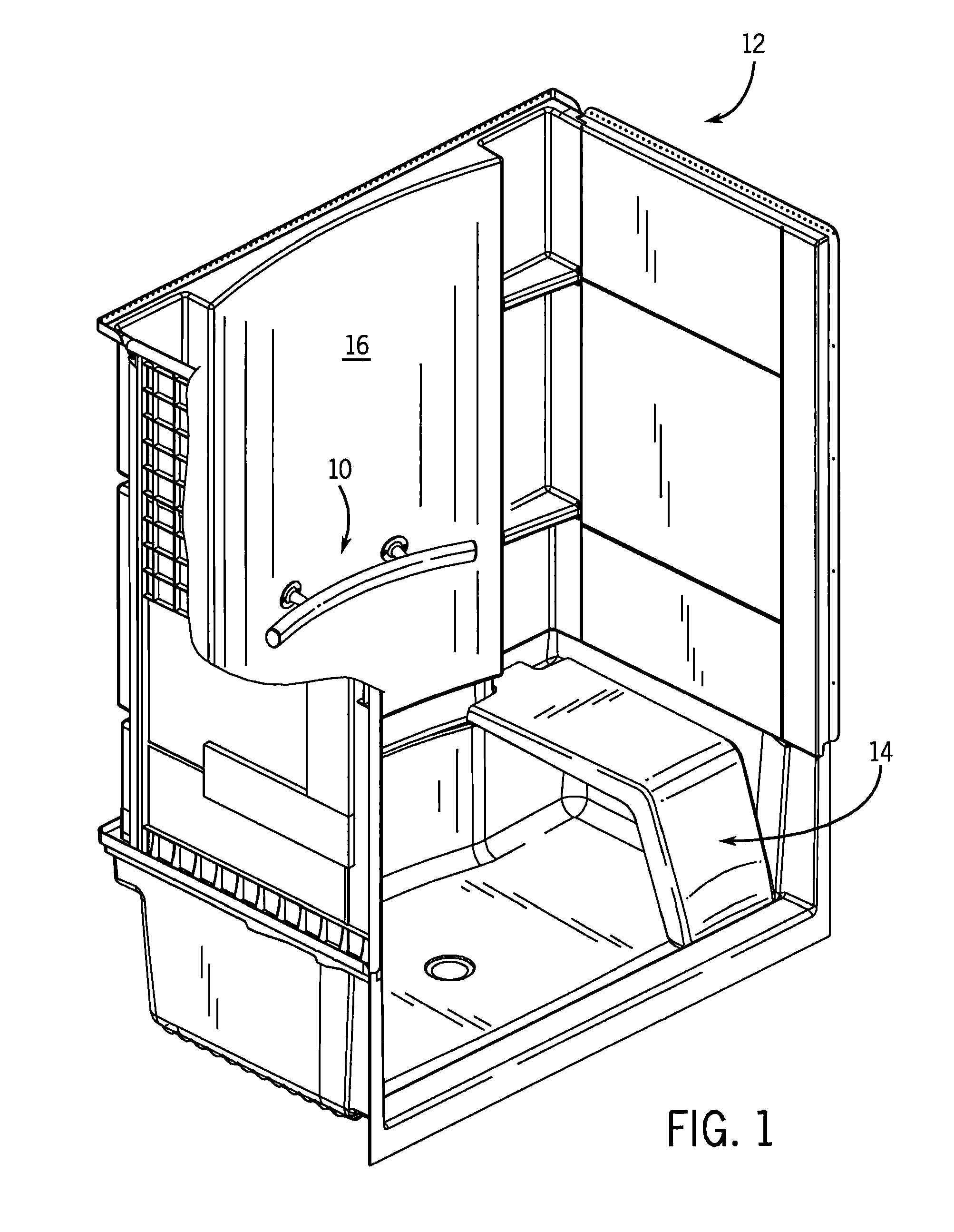
[0029]Referring first to FIG. 1, a grab bar assembly 10 according to the present invention is shown installed in a shower stall 12. The specifics of the stall are not critical. As one example, there can be a shower stall 12 that has a removable seat 14 placed on one side thereof and the grab bar assembly 10 can be mounted nearby on a rear wall 16 of the shower stall 12.

[0030]The grab bar assembly 10 can be positioned such that the grab bar assembly 10 serves as support assistance for those sitting down or standing up from the removable seat 14. Even if the removable seat 14 is removed from the shower stall 12, the grab bar assembly 10 will be located such that it may provide support assistance to an individual standing upright in the shower stall 12 or entering or exiting the shower stall 12.

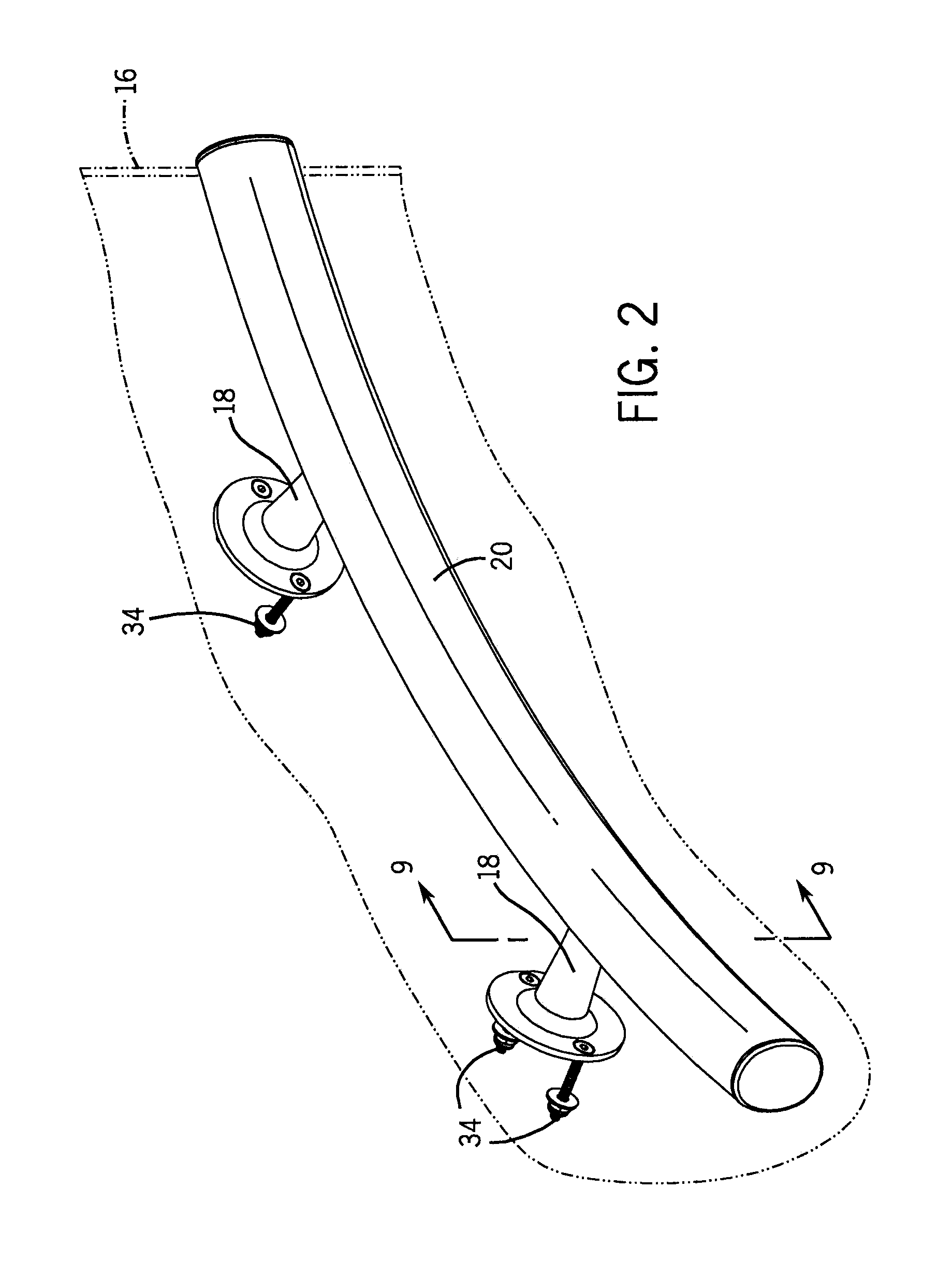
[0031]In the shower stall 12 shown, the rear wall 16 of the shower stall 12 is a slightly curved surface and the grab bar assembly 10 is also longitudinally curved to match the rear wall 16. It ...


PUM

PropertyMeasurementUnit
forceaaaaaaaaaa
relative movementaaaaaaaaaa
shapeaaaaaaaaaa

Abstract

Wall mountable accessory assemblies suitable to be mounted in a bathroom are disclosed. As an example, there is a grab bar assembly that has at least one mounting bracket, a grab bar, and a set screw. The bracket includes a rearward portion mountable to the wall and a frontal portion having a first recess which is forwardly open. The bracket also has a side catch groove structure. A projection on the grab bar is laterally slid into the catch groove structure and interfit therewith. The screw is inserted in the first recess so as to thereby drive a portion of the grab bar forward, inhibiting relative movement between the grab bar and the bracket.

Description

CROSS-REFERENCE TO RELATED APPLICATION[0001]Not applicable.STATEMENT OF FEDERALLY SPONSORED RESEARCH OR DEVELOPMENT[0002]Not applicable.BACKGROUND OF THE INVENTION[0003]This invention relates to assemblies for mounting wall mountable accessories such as grab bars, soap dishes and the like on supporting walls. It appears especially well-suited for grab bars mounted on bathing enclosure walls.[0004]Grab bars and other bathroom accessories may be mounted at various locations in bathrooms. For example, in a shower stall having a seat, it may be desirable to place a grab bar near the seat so that a user has a fixed support to assist in sitting down or standing up. Similarly, grab bars are often positioned adjacent toilets to facilitate the elderly, the disabled, and others sitting down and standing up from the toilet.[0005]However, many known grab bars are relatively heavy metal structures. These heavy metal structures may require complex mounting assemblies to keep them secured to the w...

Claims


Application Information

Patent Timeline
Patent Type & Authority Patents(United States)
IPC IPC(8): A47B96/00
CPCA47K17/022A47K2201/02Y10T29/49947
Inventor GARRELS, CLAYTON C.SPANKOWSKI, THOMAS M.
Owner KOHLER CO
Why Eureka
Try Eureka