
Indoor unit of air conditioner

a technology for air conditioners and units, applied in the field of indoor units of air conditioners, can solve the problems of dust scraping from air filters by bristles, and achieve the effects of preventing degradation of dust removal performance, high dust removal performance, and increasing the amount of trapped dus

Active Publication Date: 2013-09-03
DAIKIN IND LTD
View PDF13 Cites 6 Cited by
  • Summary
  • Abstract
  • Description
  • Claims
  • Application Information

AI Technical Summary

Benefits of technology

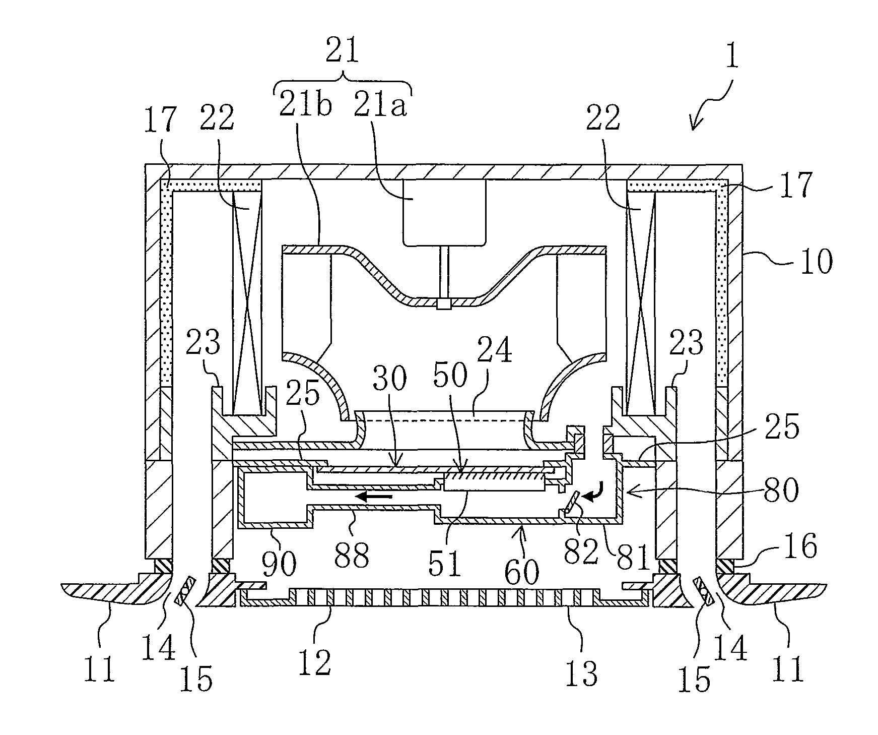
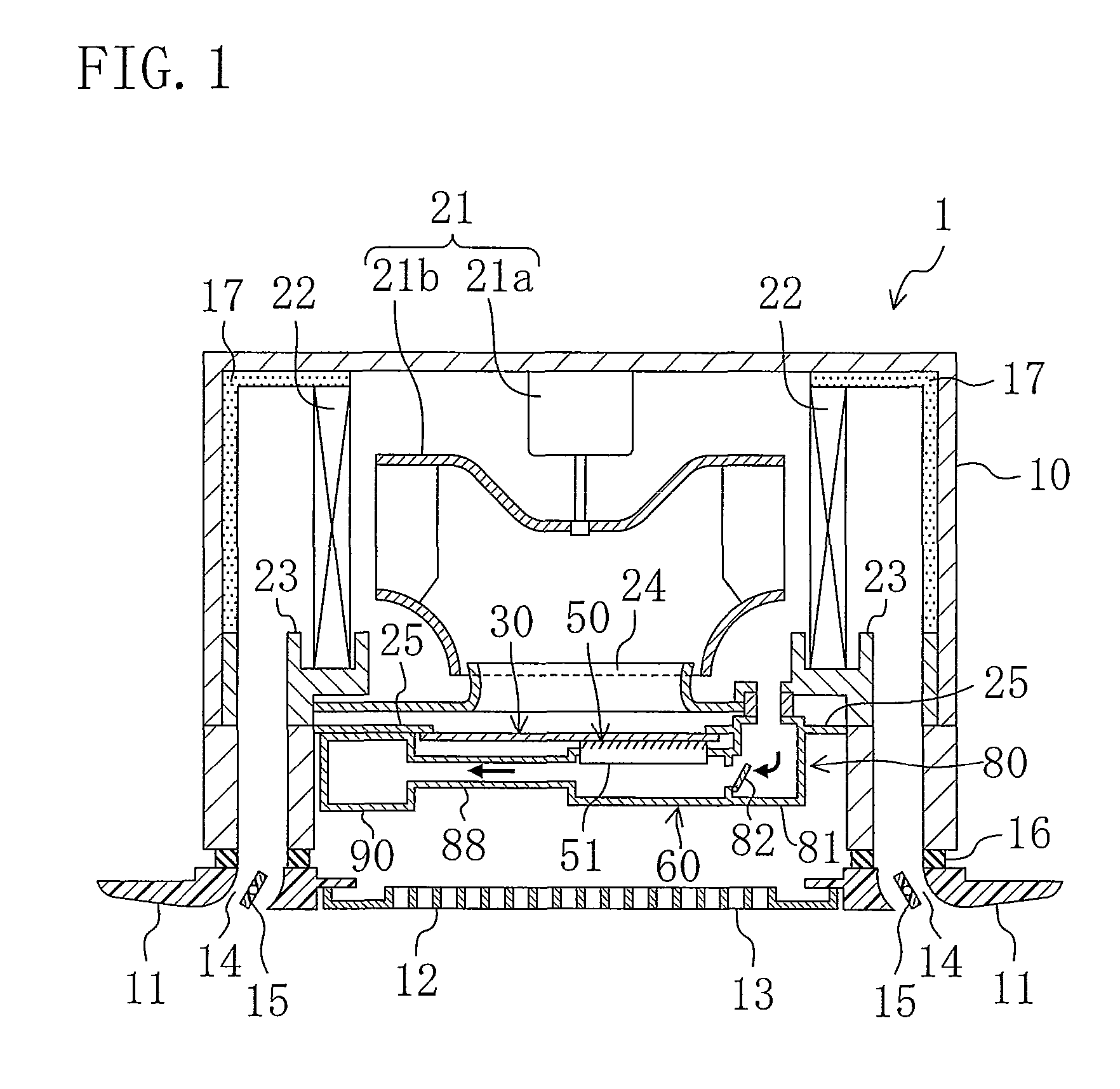
[0028]As described above, in the first and second aspects, scraping operation of scraping dust with the brush member (51) is performed on the predetermined area of the air filter (30) at each time. After each scraping operation, dust on the brush member (51) is removed by the cleaning brush member (52). Specifically, the air filter (30) and the brush member (51) are intermittently moved relative to each other for the entire air filter (30). At each stop of the intermittent movement, dust on the brush member (51) is removed by the cleaning brush member (52). That is, in these aspects, dust removal from the air filter (30) and dust removal from the brush member (51) are alternately performed for the entire air filter (30). Accordingly, the area of the air filter (30) from which dust is scraped by the brush member (51) at each time can be reduced. The amount of dust scraped by the brush member (51) at a time has a limitation. In view of this limitation, the area from which dust is scraped by the brush member (51) at a time is reduced, thereby preventing degradation of the dust removing performance of the brush member (51) due to an increase in the amount of trapped dust, and further, a failure in scraping dust by the brush member (51) when the amount of trapped dust reaches its maximum. Accordingly, a high dust removing performance (i.e., dust scraping capability) of the brush member (51) can be maintained for the entire air filter (30). As a result, the efficiency in removing dust from the air filter (30) can be increased, thereby ensuring dust removal from the entire air filter (30).
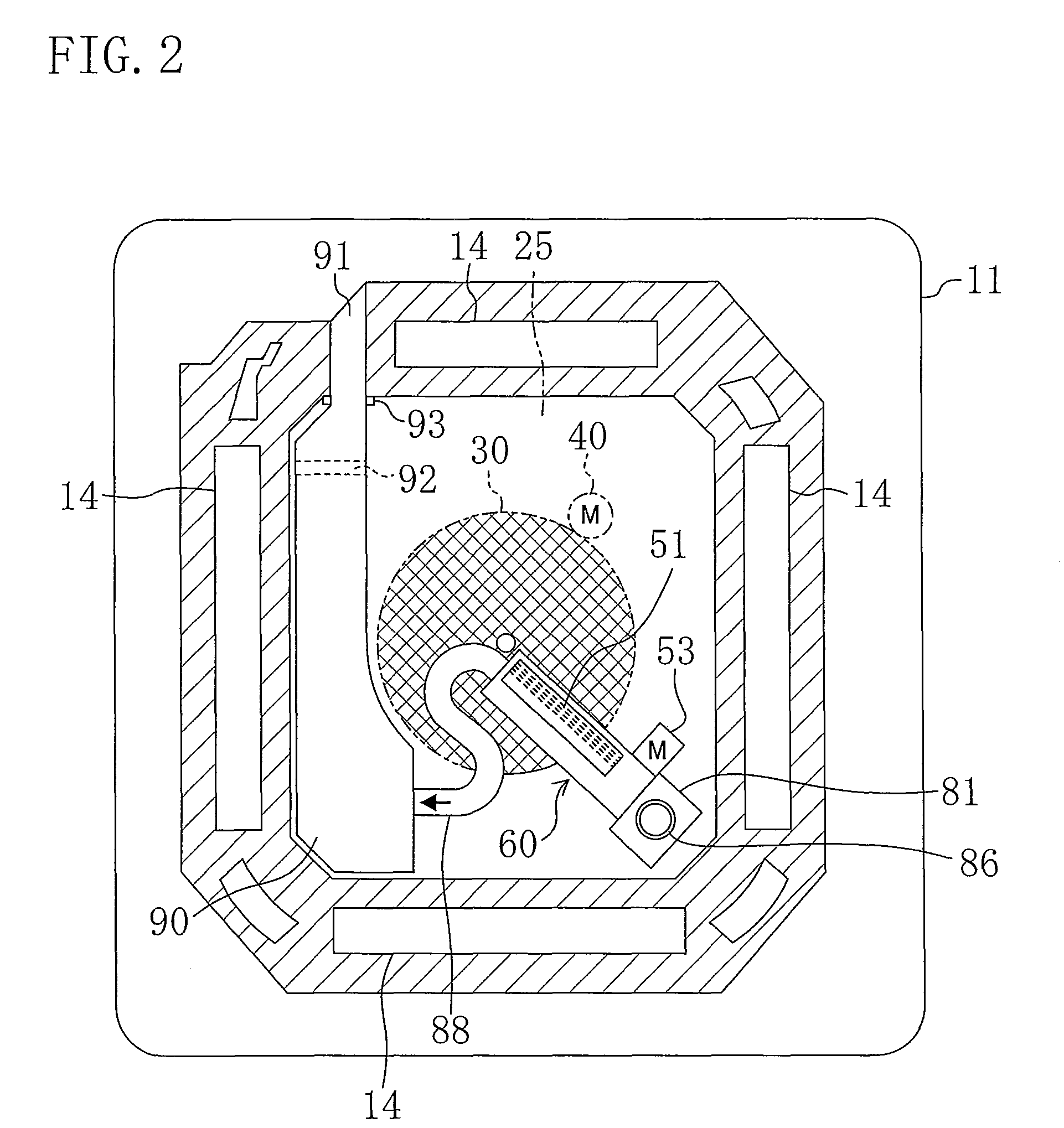
[0029]In the third aspect, the air filter (30) having a disc shape is rotated by a predetermined rotation angle relative to the brush member (51) at each time, thereby intermittently moving the air filter (30) and the brush member (51) relative to each other. Accordingly, unlike a case where the air filter (30) having a rectangular shape is slidably moved, it is unnecessary to provide space for moving the air filter (30). This configuration can reduce the size of the indoor unit.
[0030]Further, in the fourth aspect, the amount of intermittent relative movement of the air filter (30) and the brush member (51) is adjusted depending on the amount of dust attached to the air filter (30). Specifically, in this aspect, the area of the air filter (30) from which dust is intermittently removed is adjusted depending on the amount of dust attached to the air filter (30). Accordingly, when the amount of dust attached to the air filter (30) is large, the amount of the relative movement (i.e., the predetermined area) at each time is reduced to reduce the area from which dust is scraped by the brush member (51) at each time. In this manner, the amount of dust scraped by the brush member (51) at each time decreases, thereby ensuring that degradation of the dust removing performance of the brush member (51) or failure in scraping dust by the brush member (51) is avoided. As a result, dust removal from the entire air filter (30) is further ensured.
[0031]In the fifth aspect, after a series of cleaning operation in which the air filter (30) is rotated to remove dust from the air filter (30), dust on the brush member (51) is removed by the cleaning brush member (52). Accordingly, at a start of next cleaning operation, no dust is attached to the brush member (51). Thus, at the start of cleaning operation for the air filter (30), a high dust removing performance can be obtained. As a result, the time necessary for cleaning the air filter (30) can be reduced.
[0032]In the sixth aspect, the bristle portion (51b) of the brush member (51) is made of pile fabric. Accordingly, since the bristle portion (51b) has short bristles, it is possible to ensure removal of dust from the air filter (30), while reducing the area occupied by the brush member (51).
[0033]In the seventh aspect, the bristle portion (51b) of the brush member (51) is made of inclined pile fabric in which bristles of the bristle portion (51b) are inclined in a direction opposite a direction of relative movement of the air filter (30). This configuration ensures removal of dust from the air filter (30). As a result, it is possible to increase the efficiency in removing dust from the air filter (30), while reducing the area occupied by the brush member (51).
[0034]In the eighth aspect, the cleaning brush member (52) includes the bristle portion (52b) made of inclined pile fabric in which bristles of the bristle portion (52b) are inclined in a direction opposite the inclination of the bristles of the bristle portion (51b) of the brush member (51). This configuration ensures removal of dust from the brush member (51).
[0035]In the ninth aspect, the air filter (30) is temporarily rotated in the same direction as the inclination of the bristles of the bristle portion (51b) of the brush member (51), and then is stopped. This operation ensures trapping (attachment) of dust almost separated from the air filter (30) to the bristle portion (51b) of the brush member (51). Accordingly, it is possible to ensure removal of dust, without failing in removing dust from the air filter (30). As a result, the efficiency in removing dust can be increased.
[0036]In the tenth aspect, the dust container (60) configured to contain dust removed from the air filter (30) is provided, and dust in the dust container (60) is transferred to a predetermined place, together with air blowing from the indoor fan (21). This configuration eliminates the need for additionally providing a transfer section such as a suction fan in order to easily transfer removed dust to a place where the dust can be easily disposed. In this manner, it is possible to increase the efficiency in disposing dust removed from the air filter (30) without an increase in the size of the unit.

Problems solved by technology

In this indoor unit, both of the air filter and the rotating brush rotate with the bristles of the rotating brush in contact with the upstream surface (i.e., the lower surface) of the air filter, thereby causing dust to be scraped from the air filter by the bristles.

Method used


Image

  • Indoor unit of air conditioner
  • Indoor unit of air conditioner
  • Indoor unit of air conditioner

Examples


embodiment

—Third Variation of

[0137]Then, a third variation of the embodiment will be described. Although not shown, in this variation, the rotation angle of the air filter (30) in the “dust removal operation” of the filter cleaning operation is adjusted. Specifically, in this variation, the rotation angle of the air filter (30) (i.e., a predetermined area from which dust is intermittently removed) in the “dust removal operation” is adjusted depending on the amount of dust attached to the air filter (30).

[0138]In this variation, when the amount of dust attached to the air filter (30) is large, for example, the rotation angle of the air filter (30) is reduced. That is, when the amount of dust attached to the air filter (30) is large, the amount of rotation of the air filter (30) at each time is small, and thus, a small area of the air filter (30) passes over the rotating brush (51) at each time. Consequently, the area from which dust is scraped by the rotating brush (51) at each time is small. ...


PUM

PropertyMeasurementUnit
areaaaaaaaaaaa
rotation angleaaaaaaaaaa
shapeaaaaaaaaaa

Abstract

An air filter (30) intermittently rotates by a predetermined rotation angle at each time, while being in contact with a bristle portion (51b) of a rotating brush (51). Accordingly, dust on the air filter (30) is scraped by the bristle portion (51b). The brush member (51) rotates about an axial center of a shaft (51a) at each stop of the intermittent rotation of the air filter (30), to come into contact with a cleaning brush member (52). According, dust on the brush member (51) is removed by the cleaning brush member (52).

Description

TECHNICAL FIELD[0001]The present invention relates to an indoor unit of an air conditioner including a brush member configured to come into contact with an air filter to remove dust therefrom.BACKGROUND ART[0002]Among indoor units of air conditioners each having an air filter at an air inlet, those provided with a dust removing section for removing dust trapped on the air filter have been known.[0003]In an indoor unit shown in PATENT DOCUMENT 1, for example, a rotating brush as a dust removing section is provided upstream of (i.e., below) an air filter. The air filter is in the shape of a disc. The rotating brush is made of a cylindrical shaft and a plurality of bristles provided on the entire outer circumferential surface of the shaft. In this indoor unit, both of the air filter and the rotating brush rotate with the bristles of the rotating brush in contact with the upstream surface (i.e., the lower surface) of the air filter, thereby causing dust to be scraped from the air filter...

Claims


Application Information

Patent Timeline
Patent Type & Authority Patents(United States)
IPC IPC(8): B01D46/00
CPCF24F13/28F24F2003/1639F24F8/90
Inventor SAKASHITA, AKIHIKOYOKOMIZO, TSUYOSHIOKADA, MORIMICHI
Owner DAIKIN IND LTD
Learn More