Method for automatically creating a behavior pattern of a computer program for model-based testing techniques

a computer program and behavior pattern technology, applied in the field of automatically creating a behavior pattern of a computer program, can solve the problems of not being able to model a dynamic part (state chart diagram) using the known tools, and the initial investment of costs and time to develop the model is necessary

Active Publication Date: 2013-09-03
SAP AG
View PDF9 Cites 9 Cited by
  • Summary
  • Abstract
  • Description
  • Claims
  • Application Information

AI Technical Summary

Benefits of technology

[0010]In the following, general MBT concepts are briefly described. The model-based testing is a black-box testing technique and allows automatic generation of tests using appropriate models of a computer program. During these tests inputs are created and executed on the so-called “System Under Test” (SUT) which represents the corresponding system and the computer program to be tested which is running on said system. MBT is an efficient way to test software in case a model does already exist. The MBT allows an automated testing procedure to shorten schedules of software development and to improve the software quality by fully tested software. As already mentioned above, the MBT requires an existing model of the system to be tested. According to the model the expected input / output operations are generated and the tests using the MBT tools are run. Afterwards, the actual output is compared with the expected input / output and allows a quantification of the reliability of the underlying model.
[0050]As the method allows the creation of a behavior pattern (model), such as a state chart diagram, which describes the dynamic behavior of the corresponding computer program, the created model can be used in the perspective of automatically testing and analyzing via the model-based testing tools (MBT). In particular, the modeling tool enables a reverse-engineering of the state chart diagram directly from the source code which is extended by added annotations. The step of adding the annotations to the source code for creating an annotated source code file is not as time-consuming as creating the whole design according to the classical graphical way such as for example in UML via industry tools. Therefore, the described method reduces time and costs for developing a behavior pattern. As the creation of the behavior pattern is based on the source code (white-box) and the testing via model-based testing tools is based on a black-box testing, the technique of re-engineering proposed herein can be classified as “grey” re-engineering.
[0064]The generation of a superior behavior pattern by utilizing the behavior patterns of the local web services, respectively, allows improving the security of composite web services. As the behavior pattern of each local web service is implicitly embedded in the source code of the respective local web service it can be integrated in a superior source code of a superior web service which utilizes the respective source codes of the local web services. Thus, a superior behavior pattern can be created which is depicting the superior web service. Such a fusion can be performed using model fusion techniques or other appropriate techniques.
[0067]Furthermore, the behavior pattern of the local / superior web service allows collecting traces of a running web service to verify, if the security behavior of the system is the same as the one being defined by the annotations. By this way attacks on the running system can be detected by animating the model and comparing the behavior of the running system and the behavior of the model.

Problems solved by technology

However, an initial invest of costs and time to develop the models is necessary, as the models have to be designed manually via design software.
It is often the case that also for existing computer programs no models are available, so they have to be created afterwards by using reverse-engineering tools.
However, only static models (class diagrams) can be created, but it is not possible to model a dynamic part (state chart diagram) by using the known tools.
However, none of these tools is able to create a state chart diagram, such as a UML state chart diagram, which is needed to allow an automated model-based testing (MBT).
Thus, state chart diagrams have to be drawn manually using design software, such as a UML design software, but it is not possible to generate the state chart diagram automatically.
Re-engineering tools, which are using one of these techniques, are not usable to model a dynamic part of a computer program, namely to generate a state chart diagram since none of these tools introduces any annotations for enabling a reverse-engineering of state chart diagrams.
A prediction of distributed attacks is not possible by using a local behavior pattern.

Method used


Image

  • Method for automatically creating a behavior pattern of a computer program for model-based testing techniques
  • Method for automatically creating a behavior pattern of a computer program for model-based testing techniques
  • Method for automatically creating a behavior pattern of a computer program for model-based testing techniques

Examples


Embodiment Construction

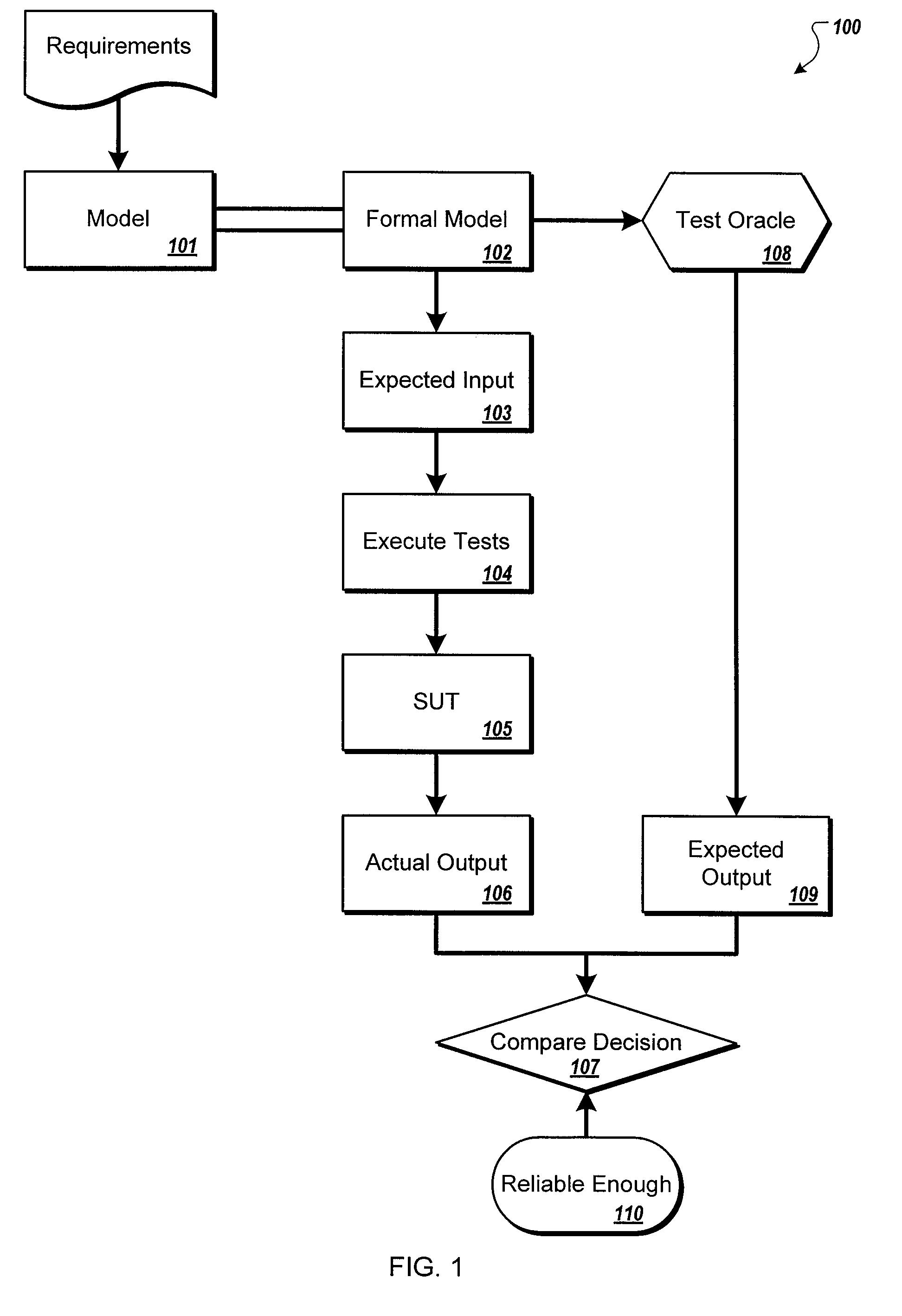
[0088]FIG. 1 shows a schematic diagram of the model-based testing technique (MBT) which is a black-box testing technique. Using the model-based testing technique, a model 101 of a computer program representing a corresponding system is transferred into a formal model 102 used to design the system to be tested by means of one or more tests. Therein, the model 101 is a model, which is designed in a graphical way (containing boxes and text) and the formal model 102 is usable for processing purposes and contains for example a finite state machine. Afterwards the expected input 103 for the tests to be performed is defined, generated and provided. Furthermore, a test oracle 108 is generated which specifies a source of expected results and an expected output 109 is defined therefrom. Generally speaking, a test oracle is a mechanism that verifies that a corresponding application (here the underlying computer program) has behaved correctly. One of the great benefits of model-based testing is...


PUM


Abstract

A method is provided for creating a behavior pattern of a computer program which comprises at least one source code with a plurality of program operations which are arranged in a logical succession and the source code is provided with annotations. Each annotation is referencing to a respective program operation and the annotations are read out automatically by a modeling tool, which is running on a processing unit and generating the behavior pattern of the computer program by arranging the annotations which have been read out according to the logical succession of the program operations and providing the generated behavior pattern, so that the generated behavior pattern can be represented via a representing unit. Furthermore, an appropriate server and an appropriate network system are provided.

Description

RELATED APPLICATION[0001]This application claims priority from European Patent Application Serial No. EP 07290 961.7, filed Jul. 31, 2007, and entitled “Method for automatically creating a behavior pattern of a computer program for model-based testing techniques,” the contents of which are incorporated herein by reference.TECHNICAL FIELD[0002]This description relates to a method for creating a behavior pattern of a computer program, in particular to a method for reverse engineering from a source code of a computer program to a state chart diagram, such as a UML state machine diagram.DESCRIPTION OF THE RELATED ART[0003]Software development is a broad area where modeling techniques and programming techniques meet. Usually, the modeling part is skipped to fulfill software development deadlines. However, the modeling part is of importance to create a model of the computer program which allows a traceability of program operations and an analysis of the computer program. Furthermore, such...

Claims


Application Information

Patent Timeline
Patent Type & Authority Patents(United States)
IPC IPC(8): G06F9/44
CPCG06F11/3608
Inventor BENAMEUR, AZZEDINEEL KHOURY, PAUL
Owner SAP AG
Why Eureka
Try Eureka