Braking device for a rope pulley of a mechanically retractable and extendable leash for walking animals

a technology of mechanical retractability and extendability, which is applied in the direction of taming devices, filament handling, web handling, etc., can solve the problems of diminishing damping effect and gentle deceleration of the rope pulley, and achieve the effect of simplifying the manufacture of the leash

Inactive Publication Date: 2013-09-10
FLEXI BOGDAHN TECHN
View PDF18 Cites 14 Cited by
  • Summary
  • Abstract
  • Description
  • Claims
  • Application Information

AI Technical Summary

Benefits of technology

[0007]According to one preferred embodiment of the invention, it is proposed that the brake disk cooperates with the rope pulley by means of a fluid. In this case, a fluid situated between the rope pulley and the brake disk generates a braking moment during a rotation of the brake disk relative to the rope pulley. Such a fluid brake is not subjected to wear and also maintains it's damping properties after an extended period of use.
[0008]Another advantage can be seen in that the damping force increases as the relative speed between the brake disk and the rope pulley increases. Due to this measure, a relatively high braking moment is generated with simple means when the brake disk is locked during a fast rotational movement of the rope pulley. A dog running away from the user therefore can be effectively stopped. Another advantage is attained, in particular, in that the leash is not ripped out of the user's hand during the braking process.
[0009]It would be possible that the rope pulley is connected in a rotationally rigid fashion to a clutch disk that rotates in a circumferential gap of the brake disk, and that the fluid is situated in the gap. Such an arrangement can be easily manufactured. In addition, the desired damping force can be achieved when the brake disk is locked by designing and dimensioning the gap between the clutch disk and the brake disk accordingly. In this case, it would be possible that at least one of the facing surfaces of the brake disk and the clutch disk is profiled. This makes it possible to additionally increase the braking moment being generated.
[0013]In the disengaged position of the brake button, the rope pulley and the brake disk are freely rotatable relative to the housing. It would furthermore be possible that the brake button is held in the first functional position by a stop that needs to be overcome by the user. This significantly improves the ease of use of the leash. The user senses a noticeable stop, at which he needs to hold the brake button in order to realize the dampened unwinding movement or wind-up movement of the rope pulley relative to the housing. This stop is overcome by increasing the pressure exerted upon the brake button such that the rope pulley is completely locked on the housing.
[0014]The brake disk may be realized in the form of a disk that is narrow in the axial direction and arranged axially adjacent to the rope pulley. Due to this measure, the housing is only insignificantly wider than that of a conventional leash without this damping option. The brake disk is realized thin relative to the axial dimension of the rope pulley. It would furthermore be possible that the brake disk features a thickened hub, in which the gap for accommodating the clutch disk is arranged. This hub may be partially arranged in the hub of the rope pulley. This measure also does not significantly widen the housing such that an appealing exterior of the leash can be achieved.

Problems solved by technology

However, this damping force does not act upon the user directly or jerkily, but rather results in a gentle deceleration of the rope pulley.
The problem in this case can be seen in that the friction surfaces wear down when the leash is used such that the damping effect diminishes in the course of time.

Method used


Image

  • Braking device for a rope pulley of a mechanically retractable and extendable leash for walking animals
  • Braking device for a rope pulley of a mechanically retractable and extendable leash for walking animals
  • Braking device for a rope pulley of a mechanically retractable and extendable leash for walking animals

Examples


Embodiment Construction

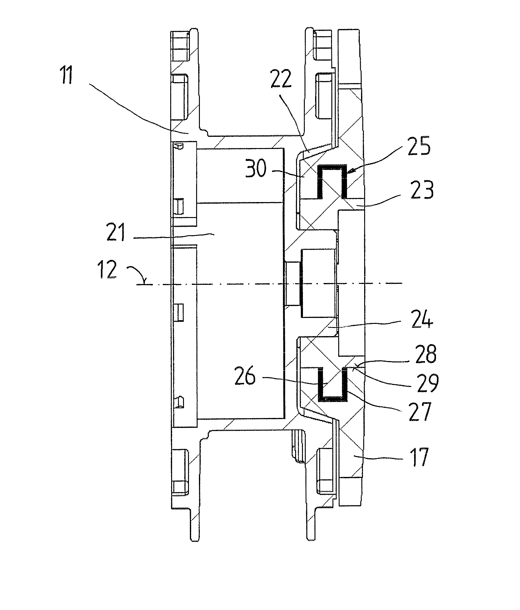
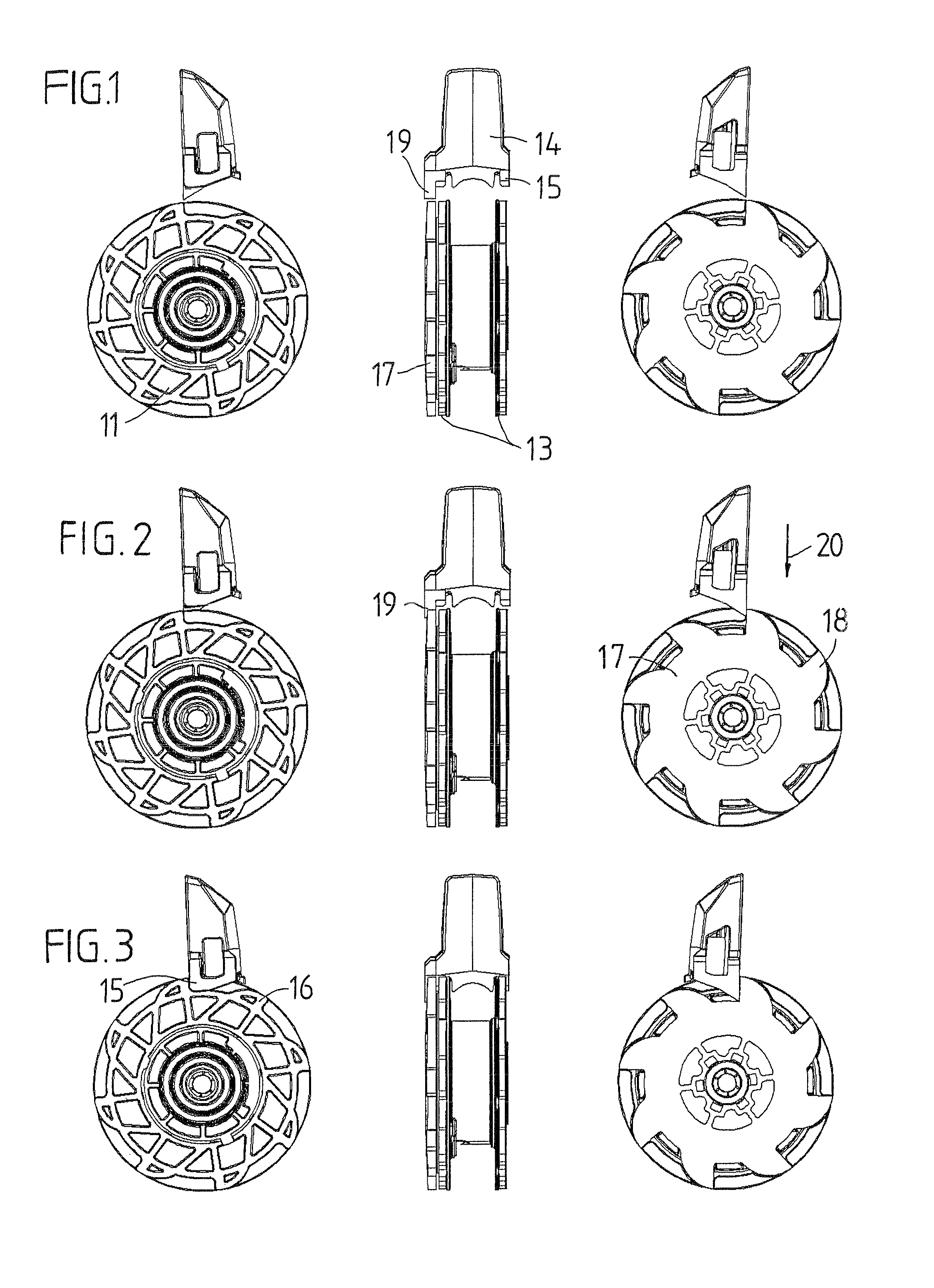
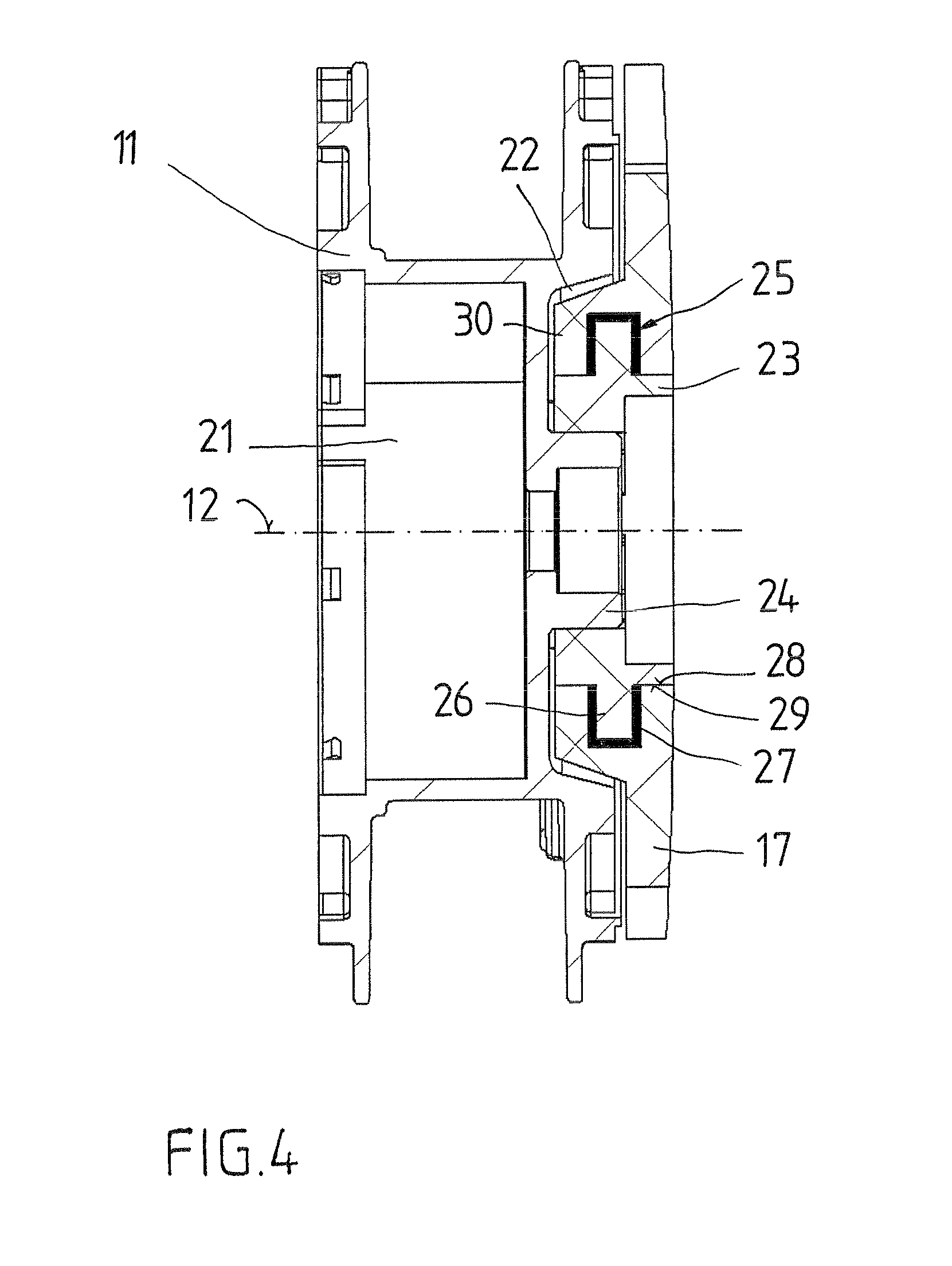
[0021]The rope pulley 11 illustrated in the drawings is supported in a housing (not shown) such that it is rotatable about an axis 12. The rope pulley 11 features two flanks 13 that are spaced apart from one another and between which the leash can be wound up. The leash extends out of the housing through an opening. A brake button 14 is arranged on the housing such that it can be moved back and forward approximately in the direction of the rotational axis against the force of a pressure spring (not shown). The brake button features locking tabs 15 that cooperate with the projections 16 on the flanks 13 of the rope pulley 11 in the second functional position of the brake button illustrated in FIG. 3. In this position, the rope pulley can no longer turn relative to the housing. The design of such a dog leash is generally known and therefore requires no further explanation.

[0022]A brake disk 17 is provided axially adjacent to the rope pulley and able to turn relative to the rope pulley...


PUM


Abstract

A braking device for a rope pulley of a mechanically retractable and extendable leash for walking animals is provided. The rope pulley is supported in a housing such that it is rotatable in an unwinding direction against the force of a spring and in a wind-up direction under the influence of the spring force and cooperates with a brake button of the braking device in order to stop rotation of the rope pulley. The rope pulley is connected to a brake disk that is rotatable relative to the rope pulley against a damping force and that can be locked to the housing.

Description

BACKGROUND[0001]The invention pertains to a braking device for a rope pulley of a mechanically retractable and extendable leash for walking animals. The rope pulley is supported in a housing such that it is rotatable in an unwinding direction against the force of a spring, and in a wind-up direction under the influence of the spring force, and cooperates with a brake button of the braking device in order to stop the rope pulley. The invention specifically pertains to a dog leash and although the following description primarily refers to a dog leash, this should not be interpreted in a restrictive sense.[0002]A dog leash of this type with a braking device is known from EP 0 941 657 B1 (which corresponds to U.S. Pat. No. 6,148,773 issued to Bogdahn). In this case, the brake button of the braking device cooperates with locking projections on the rope pulley in order to lock the rope pulley on the housing. This braking device enables the user to choose between the disengaged position of...

Claims


Application Information

Patent Timeline
Patent Type & Authority Patents(United States)
IPC IPC(8): B65H59/00
CPCA01K27/004
Inventor BOGDAHN, MANFRED
Owner FLEXI BOGDAHN TECHN
Why Eureka
Try Eureka