
Dental prosthesis system

a prosthesis and jawbone technology, applied in the field of dental prosthesis systems, can solve the problems of imperfect bores, temporary or permanent paresthesia, and difficult task of accurate placement of implants within the jawbone,

Active Publication Date: 2013-09-10
INSTITUT STRAUMANN AG
View PDF14 Cites 37 Cited by
  • Summary
  • Abstract
  • Description
  • Claims
  • Application Information

AI Technical Summary

Benefits of technology

The system facilitates precise and efficient implant placement, reduces surgical time, and accelerates healing by providing a reusable, cost-effective solution for guiding implant placement and supporting prostheses, thereby minimizing complications and improving the accuracy of dental implant procedures.

Problems solved by technology

Accurate placement of the implants within the jawbone is a difficult task.
However, this method can readily result in imperfect bores due to space limitations associated with working inside a patient's mouth.
If the drilling axis is not properly chosen, the installed implants might cause damage to the tissues and muscle surrounding the area of implantation and subsequently cause temporary or permanent paresthesia.
Furthermore, other problems can result from flawed or imperfect implant holes, such as uneven force distribution, insufficient bone growth around the implant, secondary infections, and ultimately, implant failure.
Each surgical stent commonly used is custom-built and these devices are only useful for a single patient, are costly to fabricate, and they require a number of intermediary office and laboratory steps to take an impression of the patient's arch and create a cast model from which the surgical stent is formed.
The procedure for manufacturing dental implant superstructures as is conventionally known in the art is time-consuming and sometimes results in imperfect structures or defects in the visual appearance of the dentures to be placed over the superstructure.

Method used


Image

  • Dental prosthesis system
  • Dental prosthesis system
  • Dental prosthesis system

Examples


Embodiment Construction

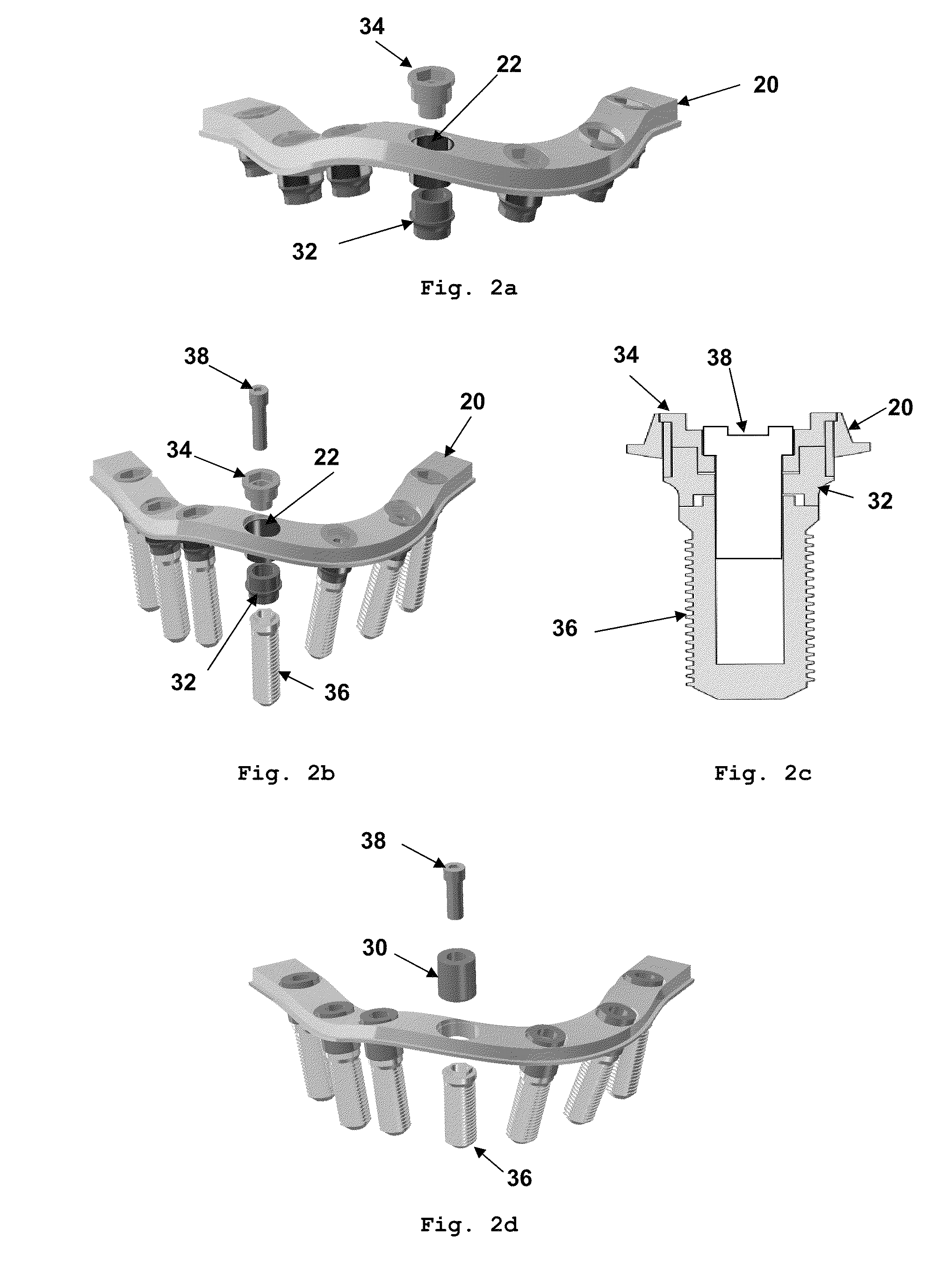
[0046]It is disclosed herein a dental implantation system that comprises components that can be used during surgical procedure and / or during prosthetic restoration.

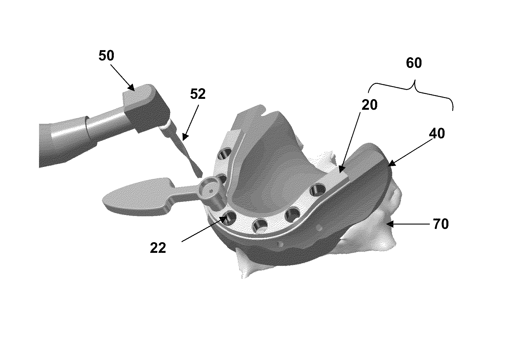
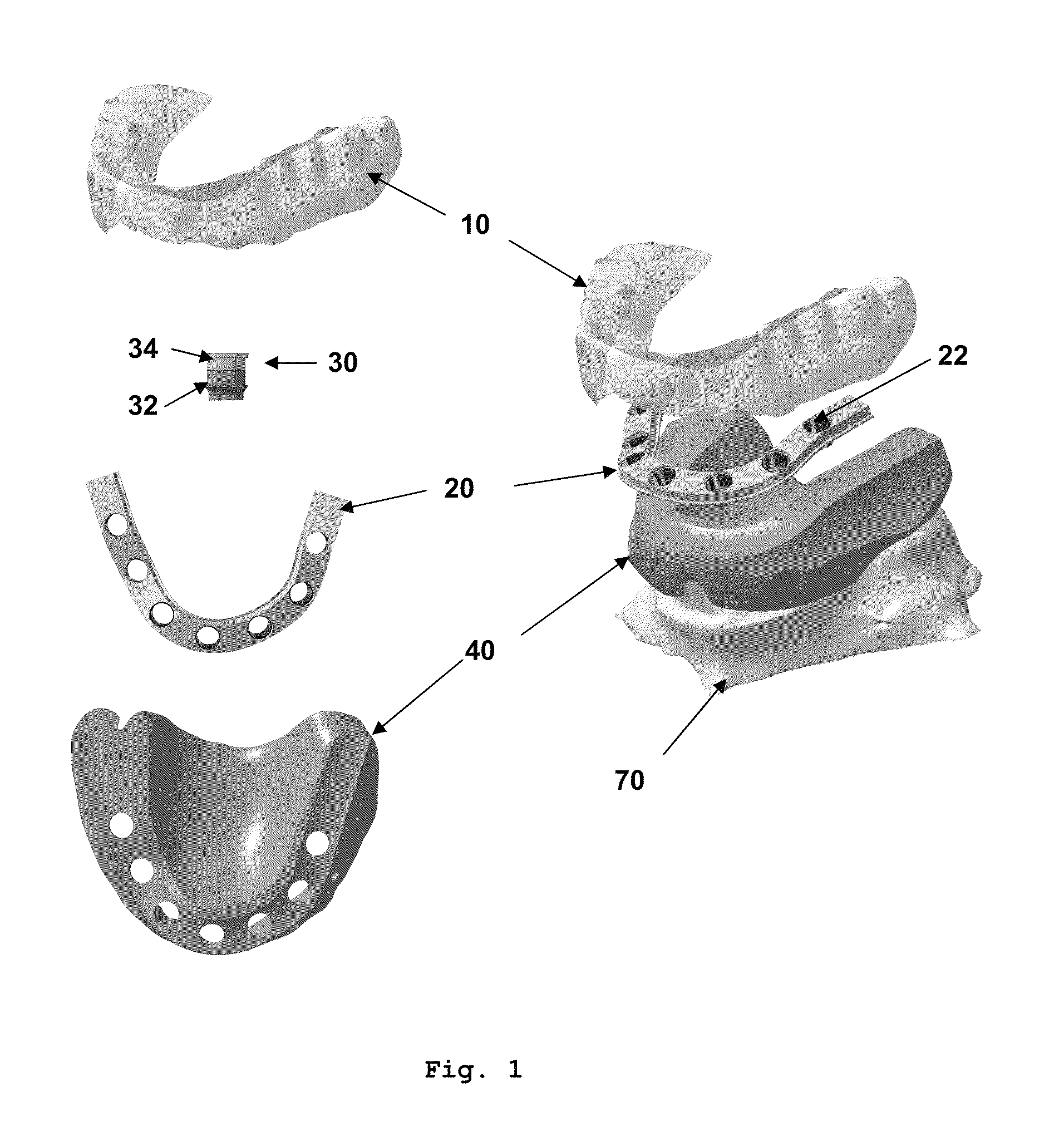
[0047]As illustrated in FIG. 1, the dental implant system comprises a prosthesis 10, a primary bar 20, and a base-plate 40. When combined, these parts represent a replica of the patient's old prosthesis or wax-up of the future denture of the patient.

[0048]When combined to the base plate 40 and primary bar 20 (FIG. 3b), the prosthesis 10 is used to precisely position the drilling guide 60 into the patient mouth. The prosthesis 10 can be made of all materials allowing some resemblance to aesthetic teeth and gum, such as pink / white acrylic, plastic or porcelain.

[0049]The primary bar 20 disclosed herein is planed prior to the surgery as a function of computer 3D models of the patient's gum surface, dentures (e.g., patient's old prosthesis or wax-up of the future denture). Once it is positioned on the base-plate 40, the primar...


PUM


Abstract

A dental prosthesis system and a method of using same having a prosthesis, a primary bar, and a base-plate. The primary bar is adapted to be received on the implants and to be used as a superstructure for supporting the prosthesis and / or a verification jig. The base-plate has a shape adapted to be received on the patient's gum surface, having at least one hole each in alignment with a corresponding one of the aperture of the primary bar when the primary bar is seated on the base-plate, each hole of the base-plate correspond to the position of each implant hole, the base-plate supporting the primary bar to form a drilling guide for guiding the drilling of implants holes in the patient's jawbone, an impression matrix for creating a physical model of the patient's mouth with implants, and / or a superstructure when removable cylinders are attached to the primary bar.

Description

CROSS-REFERENCE TO RELATED APPLICATION[0001]This patent application claims priority on U.S. Provisional Patent Application No. 61 / 145,264, filed on Jan. 16, 2009.TECHNICAL FIELD[0002]The present application relates to a dental prosthesis system comprising a drilling guide, a prosthesis, a primary bar, and a base-plate.BACKGROUND ART[0003]The use of dental prostheses with dental implants secured in the upper or lower jawbone is well known in the art. Accurate placement of the implants within the jawbone is a difficult task. The dental surgeon typically has difficulty deciding on a drilling axis for the implants since the ideal position for the implants should be decided with knowledge of the jawbone structure into which the implant is to be inserted, and with knowledge of the position within the jawbone structure of the nerve tissue, the gum surface and the required position and dimensions of the false teeth or dentures to be supported by the dental implant.[0004]The conventional sur...

Claims


Application Information

Patent Timeline
Patent Type & Authority Patents(United States)
IPC IPC(8): A61C19/04
CPCA61C1/084A61C8/0048B33Y80/00
Inventor POIRIER, MICHELWAGNAC, ERIC
Owner INSTITUT STRAUMANN AG
Learn More