
Decorative sort can recycling system

a recycling system and decorative technology, applied in the field of storage containers, can solve the problems of lack of education about recycling

Inactive Publication Date: 2013-09-17
RODRIGUEZ LAURA
View PDF13 Cites 6 Cited by
  • Summary
  • Abstract
  • Description
  • Claims
  • Application Information

AI Technical Summary

Benefits of technology

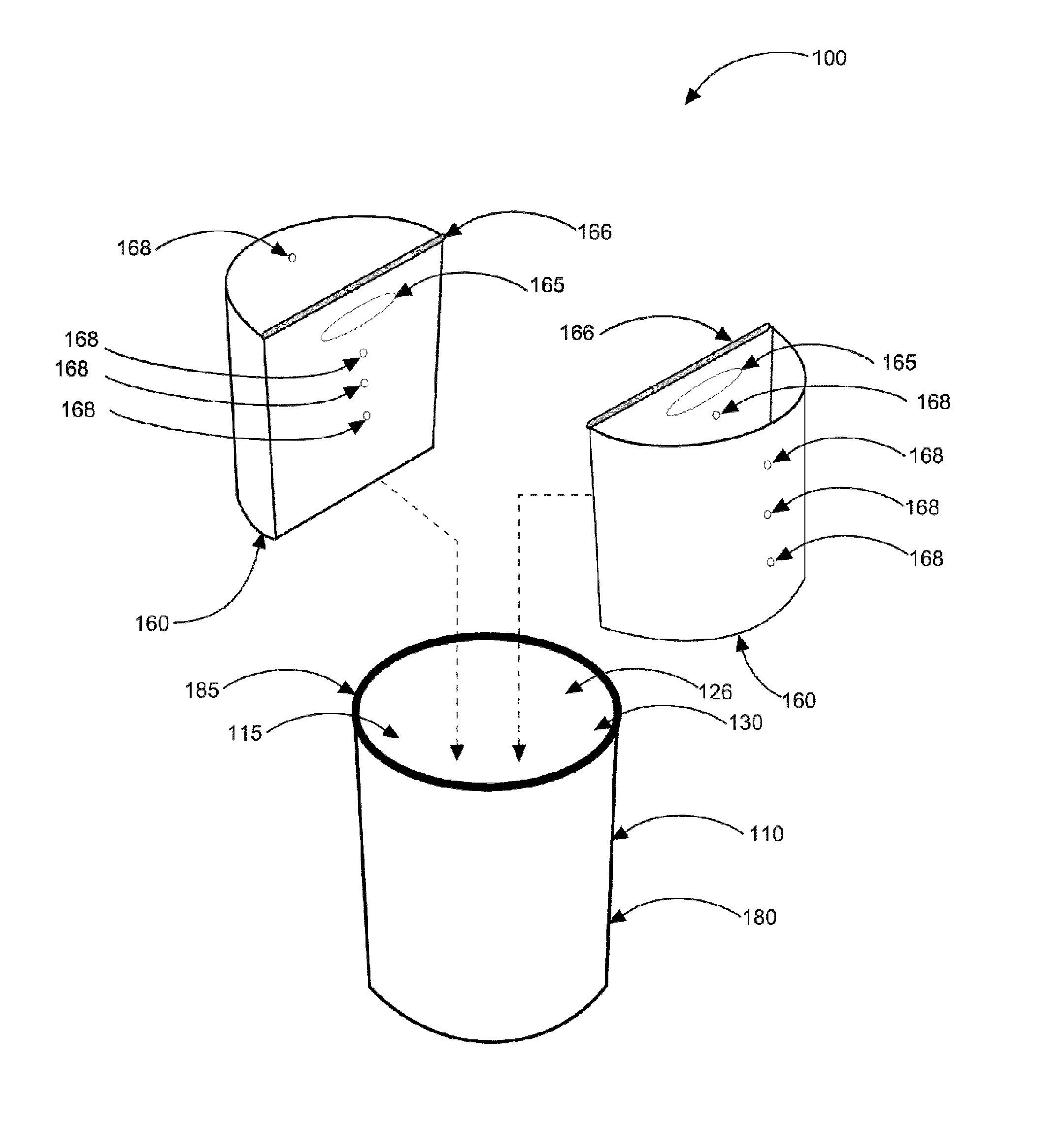
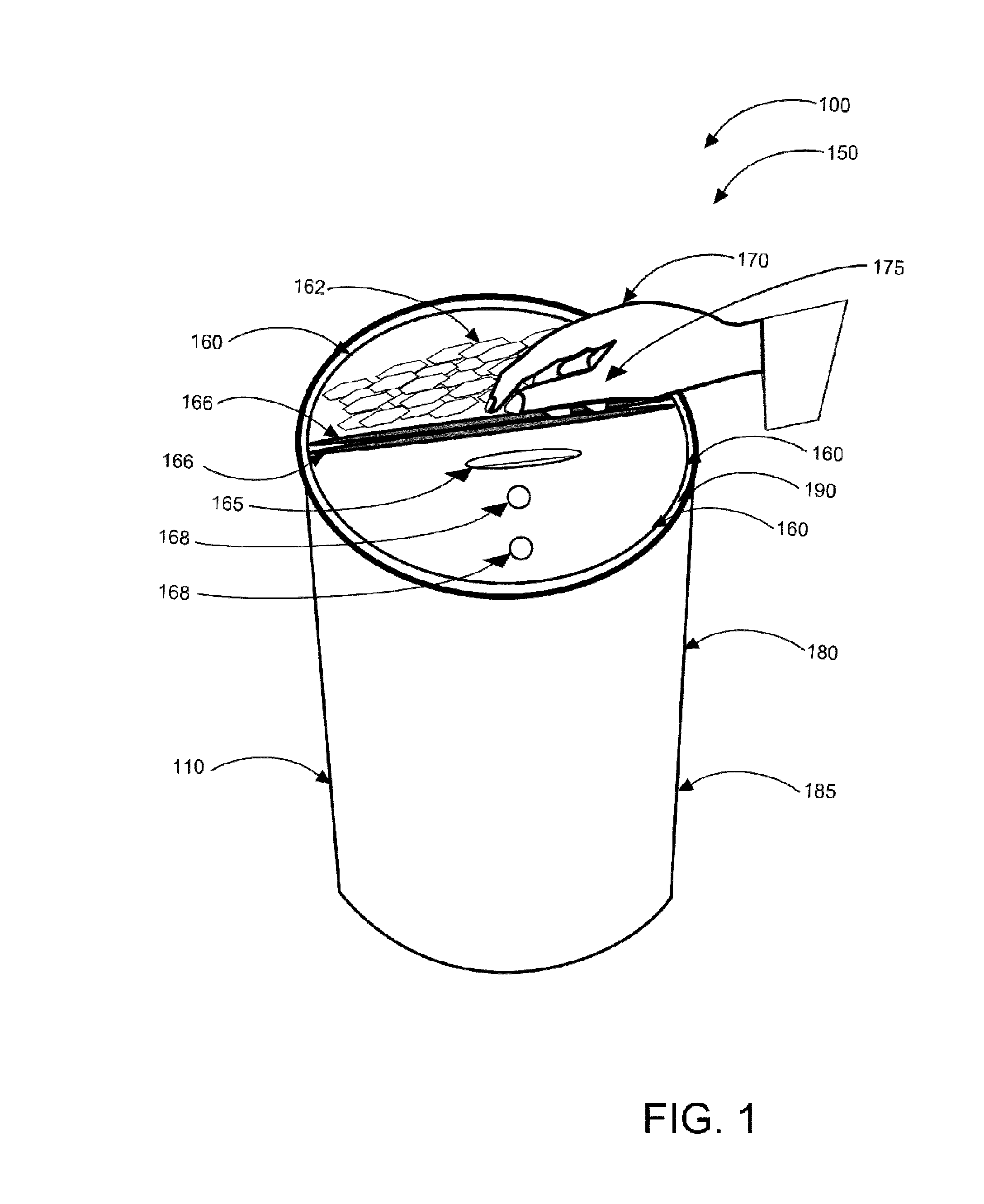
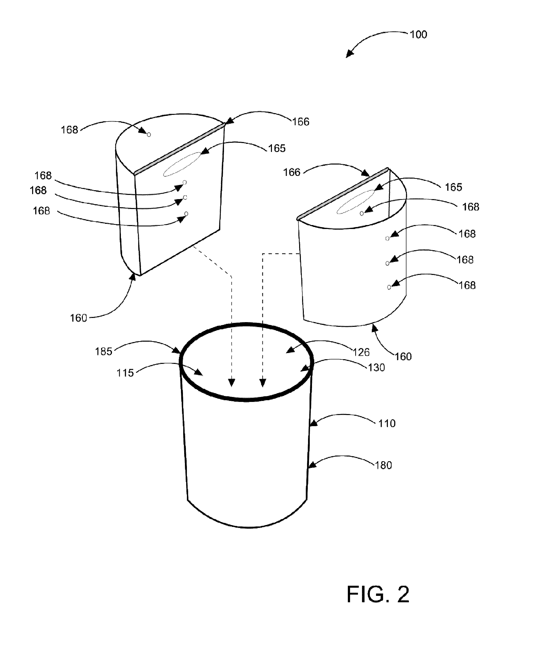
The present invention provides a novel refuse container system that solves the problem of not being able to conveniently and effectively separate recyclable trash from non-recyclable trash in every room of the house. The system is designed to be aesthetic, discreet, educational and motivational in nature. It is easy to use, with a wide variety of materials and designs available. The system includes an outer receptacle in the shape of a slightly tapered cylinder with a top opening and an inner body comprising an inner surface and an outer surface. The inner volume is able to receive cylindrical troughs with half-moon profiles, the bottom of which has a small space between the handle surfaces. The system also includes a flat bottom raised off the floor through the use of a small raised diameter rim on the bottom surface, smooth, rounded edges on the consumer contact points, and a contoured handle design for easy use. The system allows for variation in overall size, shape, and number of inner receptacle compartments. The interior recycle can inserts fit down into the outer receptacle, providing a neater profile that occupies less space and is easier to keep clean. The system also includes a carefully contoured profile of the back to back handle surfaces to create a small space where the inserts meet.

Problems solved by technology

According to research, the two main reasons people don't recycle are: 1) lack of convenience, and 2) lack of education about recycling.

Method used


Image

  • Decorative sort can recycling system
  • Decorative sort can recycling system
  • Decorative sort can recycling system

Examples


Embodiment Construction

[0031]As discussed above, embodiments of the present invention relate to a recycle can device and more particularly to a refuse container system as used to improve the storage and removal of recyclable and disposable refuse.

[0032]Generally speaking, the refuse container system along with the outer receptacle and two nestable and duplicate interior recycle can inserts provides households with a suitable means for separating their recyclable refuse from their disposable refuse in every room. The invention is preferably comprised of a tapered cylindrical version. Within the device are stored two nestable and duplicate interior recycle can inserts; one interior recycle can insert may be used to store recyclable refuse and the second interior recycle can insert may be used to store disposable refuse (or vice versa). Alternately, they may both be used for trash or both for recyclables. Various embodiments may comprise more than two inserts. Each of the interior recycle can inserts prefera...


PUM

PropertyMeasurementUnit
diameteraaaaaaaaaa
diameteraaaaaaaaaa
distanceaaaaaaaaaa

Abstract

An apparatus for separately storing recyclable and / or disposable refuse in separate inner containers within one outer receptacle. Two nestable and duplicate interior recycle can inserts are used to separate the refuse. One interior recycle can insert may store the recyclable refuse and the second interior recycle can insert may store the disposable refuse until they are ready for emptying. Each interior recycle can insert tapers from the top periphery to the lower periphery to facilitate easy insertion and removal from the outer receptacle. Each interior recycle can insert has air holes to equalize relative air pressure such that the interior recycle can inserts may be easily removable from the outer receptacle. Each interior recycle can insert has cut-out handle and a contoured handle surface to allow easy insert to the outer receptacle and easy removal from the outer receptacle. The device replaces conventional trash cans and is useful for recycling.

Description

CROSS-REFERENCE TO RELATED APPLICATIONThe present applications are related to and claims priority from prior provisional application Ser. No. 61 / 509,429 filed Jul. 19, 2011 which applications are incorporated herein by reference.COPYRIGHT NOTICE[0001]A portion of the disclosure of this patent document contains material which is subject to copyright protection. The copyright owner has no objection to the facsimile reproduction by anyone of the patent document or the patent disclosure, as it appears in the Patent and Trademark Office patent file or records, but otherwise reserves all copyright rights whatsoever. 37 CFR 1.71(d).BACKGROUND OF THE INVENTION[0002]The following includes information that may be useful in understanding the present invention(s). It is not an admission that any of the information provided herein is prior art, or material, to the presently described or claimed inventions, or that any publication or document that is specifically or implicitly referenced is prior...

Claims


Application Information

Patent Timeline
Patent Type & Authority Patents(United States)
IPC IPC(8): B65D21/02
CPCB65F1/085B65F1/1468B65F2250/116B65F2210/1815
Inventor RODRIGUEZ, LAURA
Owner RODRIGUEZ LAURA
Learn More