Recording apparatus

a recording apparatus and recording technology, applied in the field of recording apparatuses, can solve the problems of inability to employ a layout that conserves space and inconvenience in maintenance operations, and achieve the effects of preventing a rise in the temperature of ink, saving space, and superior maintainability

Active Publication Date: 2013-01-24
SEIKO EPSON CORP
View PDF13 Cites 61 Cited by
  • Summary
  • Abstract
  • Description
  • Claims
  • Application Information

AI Technical Summary

Benefits of technology

[0007]It is an advantage of some aspects of the invention to provide a recording apparatus capable of preventing a rise in the temperature of ink and whose layout conserves space, and that has superior maintainability.
[0009]With the recording apparatus according to this aspect of the invention, air flow is produced in the periphery of the liquid receptacle by the suction port sucking the surrounding atmosphere of the liquid receptacle, which makes it possible to prevent the air heated by the heating unit from building up around the liquid receptacle. Through this, the influence of heat from the heating unit on the liquid receptacle can be reduced.
[0010]Accordingly, a configuration in which the heating unit and the holding unit are disposed near each other can be employed, which makes it possible to conserve space in the layout. Furthermore, because no restrictions are placed on the location in which the holding unit is disposed relative to the heating unit, a configuration in which the holding unit is disposed in a desired location can be employed, which makes it possible to provide a recording apparatus having superior maintainability.
[0014]According to this configuration, the opening portion that enables the liquid receptacle to be inserted into / removed from the holding unit is provided in a side surface of the holding unit and the suction port is disposed in a side surface that is near the opening portion, and thus air can also be sucked from the gap between the liquid receptacle and the holding unit via the opening portion. Accordingly, an air flow can be produced along the insertion / removal direction of the liquid receptacle, and thus the influence of heat produced by the heating unit on the liquid receptacle can be suppressed with certainty.

Problems solved by technology

However, in the stated past technique, because the ink cartridge is disposed at a distance from the heating device, it is not possible to employ a layout that conserves space.
Furthermore, there is a problem in that it is necessary to carry out operations for replacing the ink cartridge from the rear surface side of the printer, which is inconvenient in terms of maintenance operations.

Method used


Image

  • Recording apparatus
  • Recording apparatus
  • Recording apparatus

Examples


Embodiment Construction

[0028]An embodiment of a recording apparatus according to the invention will be described hereinafter with reference to the drawings. It should be noted that in the drawings used in the following descriptions, the scale of the various constituent elements has been changed in order to achieve sizes that are more visibly recognizable. In this embodiment, an ink jet printer (called simply a “printer” hereinafter) will be given as an example of a recording apparatus according to the invention.

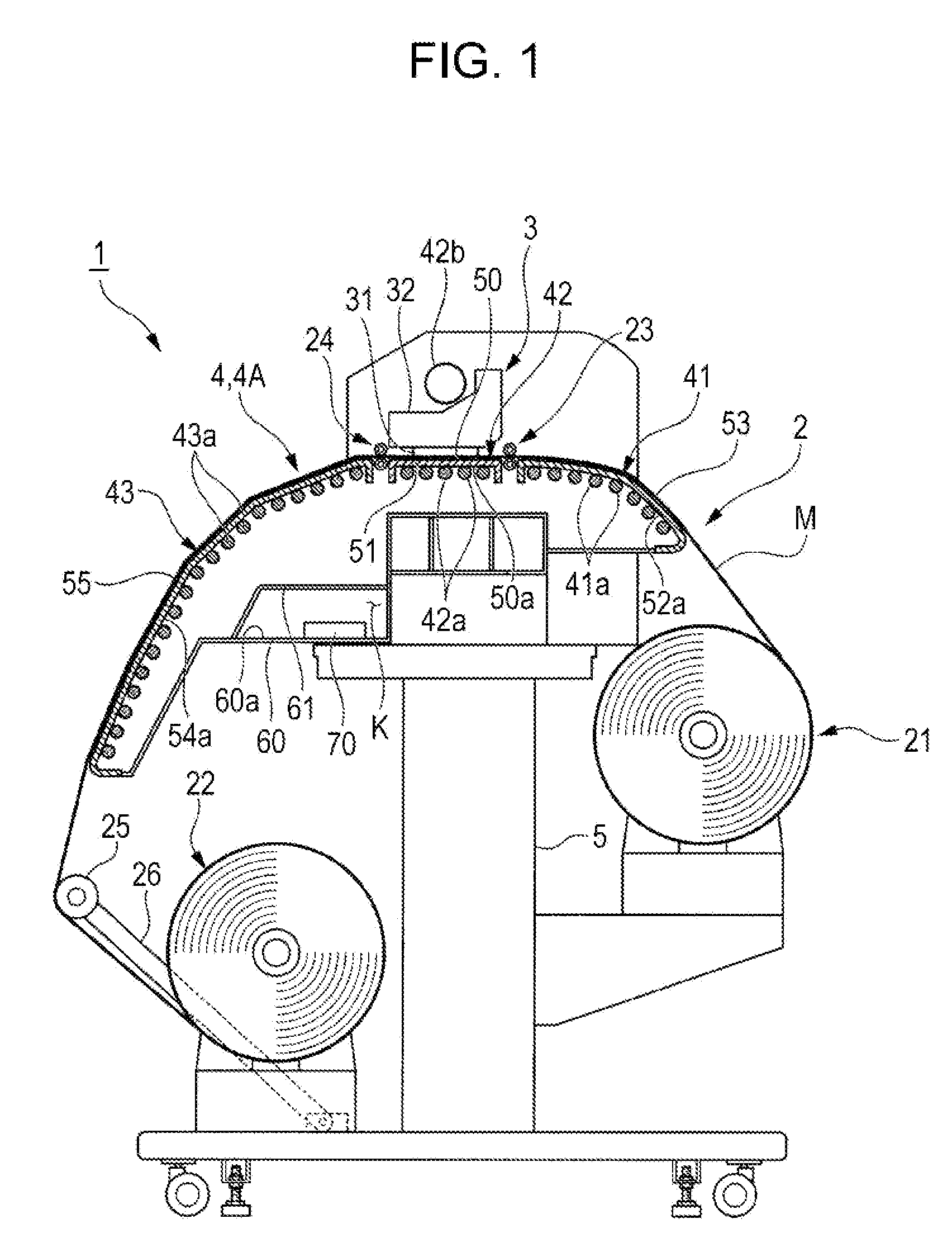
[0029]FIG. 1 is a schematic diagram illustrating a printer 1 according to an embodiment of the invention.

[0030]The printer 1 is a large-format printer (LFP) that handles a comparatively large-size medium (recording medium) M. The medium M according to this embodiment is formed of, for example, a vinyl chloride film having a width of approximately 64 inches.

[0031]As shown in FIG. 1, the printer 1 includes a transport unit 2, a recording unit 3, and a heating unit 4, where the transport unit 2 transp...


PUM


Abstract

A recording apparatus includes: a holding unit that holds a liquid receptacle containing a liquid; a recording head that ejects, onto a recording medium, the liquid supplied from the liquid receptacle held by the holding unit; a heating unit that heats the recording medium; and a suction unit that includes a suction port for sucking air to the heating unit. Here, the suction port is disposed in a location that enables the atmosphere around the liquid receptacle to be sucked.

Description

BACKGROUND[0001]1. Technical Field[0002]The present invention relates to recording apparatuses.[0003]2. Related Art[0004]Ink jet printers are known as an example of a recording apparatus that records images, text, or the like by ejecting a fluid onto a recording medium. In the case where an ink (fluid) that requires penetration drying, evaporation drying, or the like is used in such an ink jet printer, it is necessary to provide a heating device as a drying unit for drying the ink that has been ejected onto the recording medium.[0005]An ink jet printer having a structure in which ink is supplied to a recording head from an ink cartridge is known as this type of recording apparatus (for example, see JP-A-2010-188624). With such an ink jet printer, it is necessary to prevent the temperature of the ink within the ink cartridge from rising in order to maintain stable ink ejection properties. Accordingly, a configuration in which the heating device and the ink cartridge are disposed as f...

Claims


Application Information

Patent Timeline
Patent Type & Authority Applications(United States)
IPC IPC(8): B41J2/175
CPCB41J11/001B41J29/377B41J11/0085B41J11/002B41J11/00216B41J11/0022B41J11/0024
Inventor OTA, MIHOKITAGISHI, MIKIO
Owner SEIKO EPSON CORP
Why Eureka
Try Eureka