Circuit and system for driving organic thin-film EL elements

Inactive Publication Date: 2002-11-26
YEUAN JIAN JONG
View PDF7 Cites 50 Cited by
  • Summary
  • Abstract
  • Description
  • Claims
  • Application Information

AI Technical Summary

Benefits of technology

By the construction described above, when the scanning position is switched to the next scan line with a power potential and the rest of the scan lines are set to a ground potential, the parasitic capacitor of the organic thin-film EL element which emits light is charged by the scanning source via the scan line, and the parasitic capacitor of th

Problems solved by technology

The parasitic capacitor 31 within the equivalent circuit always causes a response problem, especially in a matrix of organic thin-film EL elements.
Accordingly, the prior art driving system 40 always causes problems once used in driving a matrix of organic thin-film EL elements for luminance.
The main problem is that the scanning speed will be slowed down due to the parasitic capacitors described above.
When the organic thin-film EL is used as a luminous element, this problem becomes more severe since the organic thin-film EL has a large capacito

Method used


Image

  • Circuit and system for driving organic thin-film EL elements
  • Circuit and system for driving organic thin-film EL elements
  • Circuit and system for driving organic thin-film EL elements

Examples


Embodiment Construction

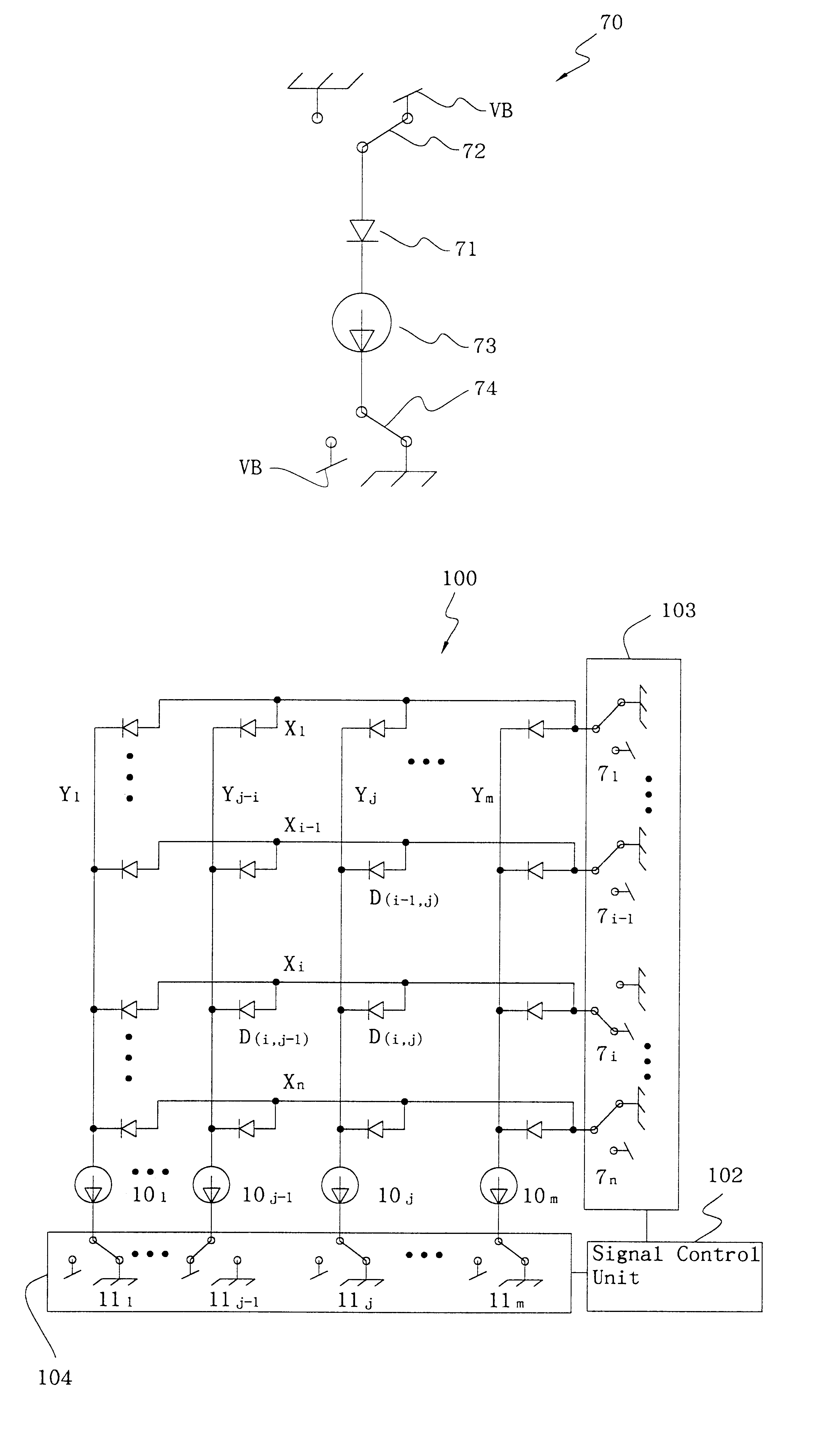
FIG. 7 shows a driving circuit 70 for an organic thin-film EL element according to a first embodiment of the present invention. In this driving circuit 70, an organic thin-film EL element 71 is connected between an anode-scanning switch 72 and a constant current source 73, and the current output from the constant current source 73 flows to a cathode data-driving switch 74. Both the anode-scanning switch 72 and cathode data-driving switch 74 are switches which are switched between a power potential and a ground potential. The anode-scanning switch 72 and the cathode data-driving switch 74 are used to control the emission of the organic thin-film EL element 71. The anode-scanning switch 72 is connected to a power potential while the organic thin-film EL element 71 is scanned and connected to a ground potential otherwise; the cathode data-driving switch 74 is connected to a ground potential while the organic thin-film EL element 71 is selected and connected to a power potential otherwi...


PUM


Abstract

The present invention discloses a circuit and system for driving an organic thin-film electroluminescent (EL) display to emit light. The driving system of the present invention can quickly respond to the point of emission when a supply voltage is applied. This driving system includes a plurality of intersecting anode and cathode lines arranged in a matrix. The anode lines are the scanning lines, and the cathode lines are the driving lines. A plurality of organic thin-film EL elements is positioned at the intersection of scanning and driving lines. Each of the organic thin-film EL elements is electrically connected to one of the scanning lines and one of the constant current sources followed by connecting to one of the driving lines. The signal control unit controls the scan lines causing at least one of these elements to emit light by executing scanning of at least one of the scan lines and, during a predetermined period of the scanning, by coupling a driving source to at least one of the driving lines in the scanning period.

Description

1. Field of the InventionThe present invention relates to a circuit and system for driving an organic thin-film electroluminescent (EL) display to emit light, and particularly to a circuit and system for driving the organic thin-film EL element to emit light at a specified constant driving current.2. Description of Related ArtThe light-emitting luminance of the organic thin-film EL elements varies when the driving current flowing into the element varies. To control the uniformity of luminance of organic thin-film EL element, the driving current flowing into the element must be controlled and maintained at a specified constant current level among the organic thin-film EL elements.FIG. 1 shows a prior art driving circuit. In FIG. 1, a constant current supply 13 intends to change the driving current, which is supplied from a power supply 11 to a light-emitting element 12. It should be noted that the light-emitting element 12 emits light when a switch 14 is open as indicated by solid li...

Claims


Application Information

Patent Timeline
IPC IPC(8): G09G3/32
CPCG09G3/3216G09G2310/0251G09G2320/0223
Inventor YEUAN, JIAN-JONG
Owner YEUAN JIAN JONG
Why Eureka
Try Eureka