Blood pressure measuring apparatus

a technology of measuring apparatus and blood pressure, which is applied in the direction of instruments, catheters, angiography, etc., can solve the problems of band to twist, large amount of blood pressure, and inability to accurately measure blood pressure,

Inactive Publication Date: 2013-09-17
WELCH ALLYN INC
View PDF125 Cites 5 Cited by
  • Summary
  • Abstract
  • Description
  • Claims
  • Application Information

AI Technical Summary

Benefits of technology

[0019]These and other needs are met by the present invention, which provides systems, methods and kits for interchangeably enabling blood pressure measurements to be performed on a patient through use of various different blood pressure measurement equipment or devices while enabling the same cuff / sleeve to be worn by the patient the entire time, if desired. In other words, through use or implementation of the systems, methods and kits of the present invention, a patient can wear the same cuff / sleeve while numerous blood pressure measurements are performed using a wide variety of manual or electronic blood pressure measurement equipment, regardless of the design or manufacturer of the various equipment, thus obviating the need to repeatedly detach a cuff / sleeve and then locate and reattach a new sleeve / cuff. Additionally, the systems, methods and kits of the present invention enable any of several pieces of blood pressure measurement equipment to be individually connected to any of multiple patients regardless of the size and type of cuff each patient is wearing and / or irrespective of the design and manufacturer of the pieces of blood pressure measurement equipment.
[0021]The first adapter (and, if present, the second adapter) enable a cuff of any size and / or type to be quickly and easily individually placed in fluid communication with any of a variety of different blood pressure measurement device so as to facilitate the process of individually taking blood pressure measurements for multiple patients. Thus, in accordance with this exemplary aspect, a truly interchangeable, versatile and easy-to-use blood pressure measurement system is provided.
[0022]Optionally, this individual interconnection can be accomplished through the use of at least one hose attachment, the attachment having a first end for connection to the second adapter and a second end for interchangeable individual connection to any of a plurality of blood pressure measuring devices. Thus, interchangeability is provided in at least two important ways. First, in lieu of replacing a cuff / sleeve in order to enable a number of blood pressure measurements to be taken from a single patient via different blood pressure measurement devices or equipment, the system of the present invention merely entails attachment of a second adapter and / or hose. Second, and in a similar vein, the hose and second adapter attachment more easily allow for blood pressure measurements to be taken from multiple patients using the same or different blood pressure measurement equipment and regardless of the size and / or type of cuffs being worn by the patients. Such interchangeability provides valuable time savings and design flexibility as compared to those systems that are currently utilized.
[0026]In yet further accordance with this exemplary aspect, the first and second adapters are releasably connected, whereby the second adapter is at least partially (and, if desired, substantially entirely) rotatable while connected to the first adapter so as to prevent or at least inhibit kinking of hose attached to the second adapter. The releasable connection between the first adapter and the second adapter can be accomplished, by way of non-limiting example, by snap fitting, friction fit, detent action, threaded engagement or by fitting a flange of the second adapter over an elastomeric lip of the first adapter. By way of another non-limiting example, the releasable connection between the first and second adapter can occur by virtue of the second adapter including recesses within which fingers or other protruding portions of the first adapter can fit, e.g., via snap fitting or detent. By way of yet another non-limiting example, the releasable connection between the first adapter and the second adapter can be accomplished by providing the second adapter with a plunger-like mechanism to expand inwardly or outwardly following a predetermined action (e.g., upon the pressing of a button or upon activation of a trigger) in order to hold or release the first adapter in / from tactile communication with the second adapter.

Problems solved by technology

Typically, the above referred to movement mechanisms are quite intricate and complex, and are akin in terms of their manufacture and precision to Swiss watches.
As the spindle deflects axially in response to the inflation of the bellows, the bent spring part is also caused to deflect, thereby causing the band to twist.
In addition, any adjustments required after assembly of the above mechanisms, such as to null the pointer or adjust the sensitivity of the device, require substantial tear down or at least some undesired disassembly.
There is still reliance, however, upon inflation and deflation of an inflatable sleeve and more particularly, there is a fluid interconnection between the interior of the sleeve and the interior of the gage housing.
Currently, there is no standard that dictates how manual or electronic blood pressure measurement devices must be designed.
The preceding situation, in turn, has created a problem in which vital time and manpower is being lost while switching between and among these different types of blood pressure measurement equipment.
Even in a best-case scenario, each round of detaching, locating and reattaching steps are inconvenient because they command the attention, however brief, of medical personnel who could otherwise be performing different tasks.
And at worst, the seconds to minutes that can be spent in locating, attaching, detaching and reattaching each new cuff / sleeve with a pre-attached hose could have life-impacting consequences for a patient.
Moreover, due to the chaos that often can be encountered when evaluating a patient in a hospital, especially in an emergency department setting, it is not uncommon for the at least one pre-attached hose that is connected to the cuff / sleeve to become kinked to an extent that would prevent further blood measurements from being taken with sufficient accuracy.
This is problematic for the same reasons noted above, plus it can introduce even more chaos into the emergency department environment.

Method used


Image

  • Blood pressure measuring apparatus
  • Blood pressure measuring apparatus
  • Blood pressure measuring apparatus

Examples


first embodiment

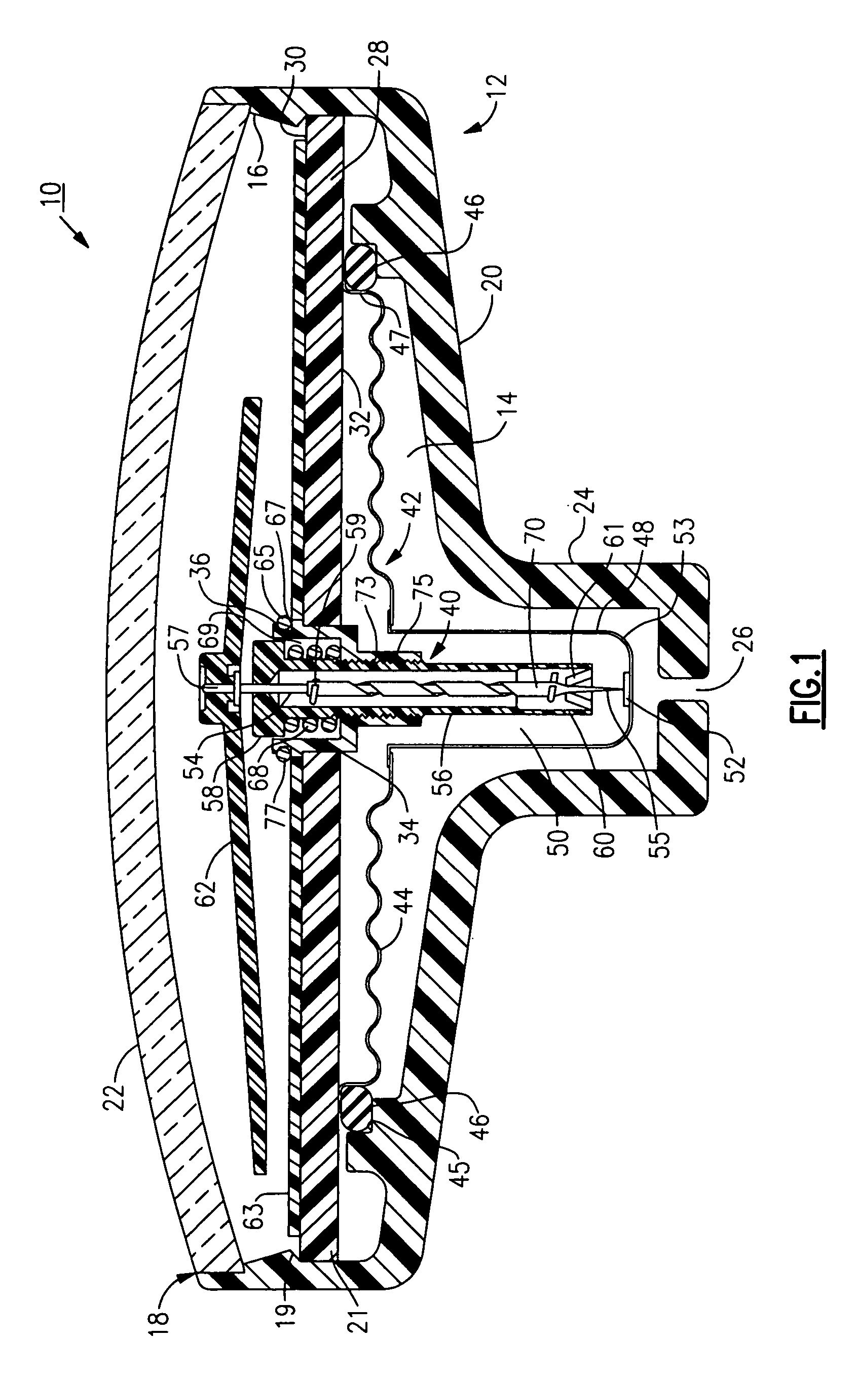
[0074]Referring to FIG. 1, there is shown a blood pressure measuring device or apparatus 10 made in accordance with the invention. The device 10 includes a substantially cylindrical gage housing 12 having an interior cavity 14 defined by a circumferential inner wall 16, an open top end 18, and a bottom end 20. A viewing window or bubble 22, made from glass, plastic, or other suitable transparent material is attached in a known manner to the open top end 18 of the gage housing 12. The bottom end 20 of the gage housing 12 has a diameter which inwardly tapers down to a narrow downwardly extending portion 24 having a bottom opening 26 serving as an inlet port for admitting a fluid. Preferably, the diameter of the narrow extending portion 24 is about one third of the diameter of the major portion of the housing 12, though it will be apparent from the following discussion that this parameter can be suitably varied depending upon the application.

[0075]The interior cavity 14 of the housing ...

second embodiment

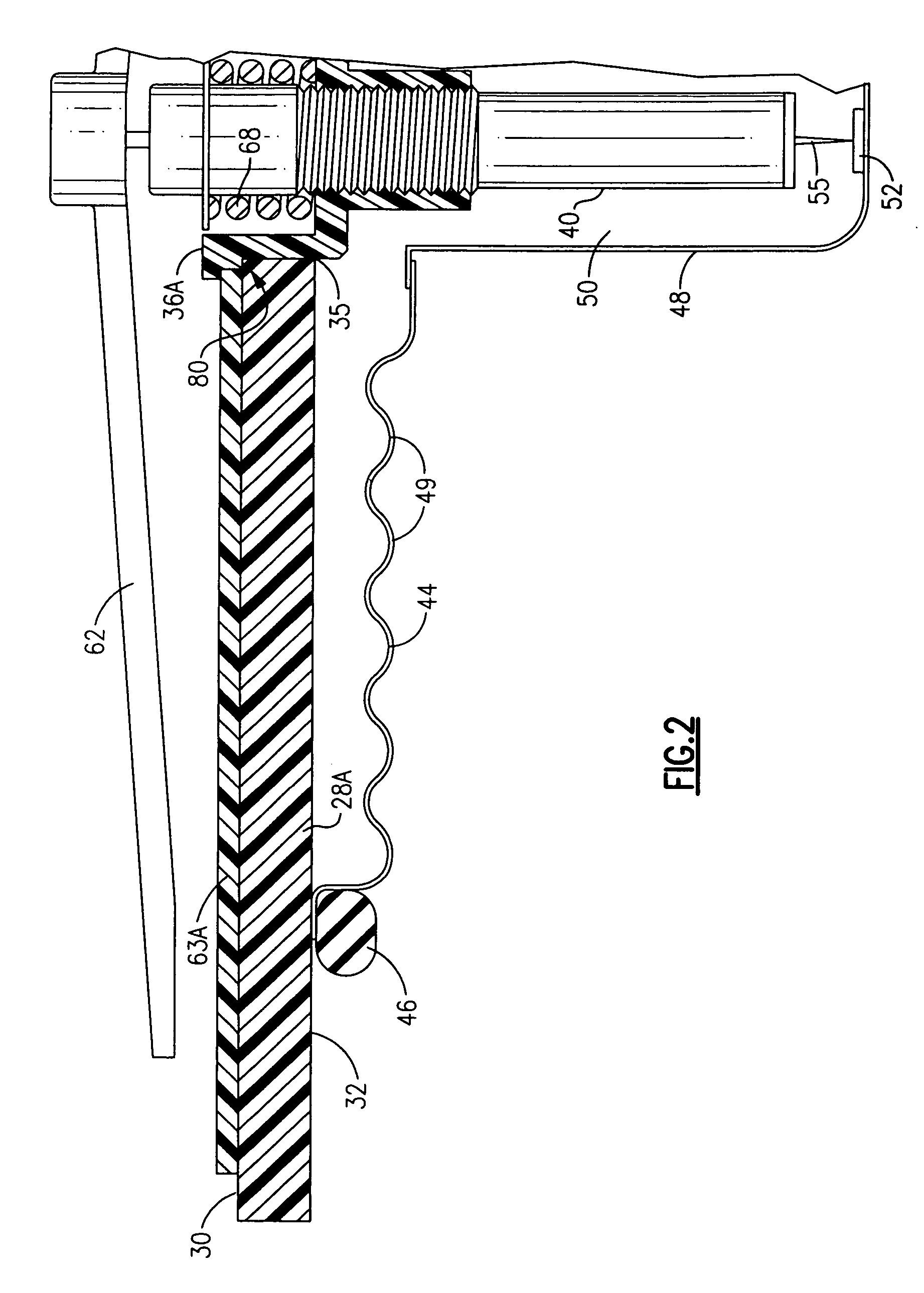
[0086]A housing design in accordance with a second embodiment is illustrated in FIG. 3. Similar parts are herein labeled with the same reference numerals for the sake of clarity. As in the preceding, the device includes a gage housing 12 having an interior cavity 14 sized for retaining a diaphragm assembly 42 that includes a diaphragm 44 having a series of wave-like surfaces 49, as well as a downwardly extending portion or pan 48. The device further includes a substantially horizontally disposed planar support plate 28, the housing 12 further having a downwardly extending narrowed portion 24. A movement mechanism 40 is disposed through a central opening 34 defined in the horizontal support plate 28 such that the bottom end 55 of an axially displaceable shaft 54 of the mechanism is disposed in proximity to a hardened contact surface 52 of the pan 48 of the diaphragm assembly 42. The diaphragm 44 in the meantime is attached, but not sealed, to the bottom facing side 32 of the horizont...

third embodiment

[0089]To further illustrate variations and referring to FIG. 4, a housing 12B made in accordance with the present invention includes a diaphragm 44B, which unlike the preceding embodiments, is a substantially vertical member having an overall width dimension that is considerably narrower than those previously described. As a result, a horizontal support plate is not required, as in the preceding.

[0090]As in the preceding embodiments, an outer edge 47B of the diaphragm 44B is sealed using an O-ring 46B or other sealing member which effectively clamps the outer edge to a shoulder of the a press-fitted sleeve 36B. The movement mechanism 40 is disposed essentially through a center opening in a press-fitted sleeve 36B and threaded into engagement therewith. The majority of the movement mechanism 40 is disposed within the cavity defined by the essentially vertical diaphragm 44B, the particular diaphragm of this embodiment having vertically disposed wave-like surfaces 49B. Adjustments to c...


PUM

PropertyMeasurementUnit
distanceaaaaaaaaaa
distanceaaaaaaaaaa
distanceaaaaaaaaaa

Abstract

Adaptive attachments used in combination with a blood pressure cuff enable various blood pressure measurements to be taken in a hospital or other setting having various single and / or dual lumen manual or electronic blood pressure measuring equipment with a single, patient-worn cuff.

Description

CROSS REFERENCE TO RELATED APPLICATIONS[0001]This application claims priority as a continuation in part (CIP) application to copending and commonly owned U.S. patent application Ser. No. 11 / 230,117, entitled BLOOD PRESSURE MEASURING APPARATUS, which was filed on Sep. 19, 2005 and claimed priority as a CIP application to U.S. patent application Ser. No. 10 / 456,704, which was filed on Jun. 5, 2003 and claimed priority as a CIP application to U.S. patent application Ser. No. 09 / 929,501, which was filed on Aug. 14, 2001, issued as U.S. Pat. No. 6,615,666 on Sep. 9, 2003, and claimed priority as a CIP application to U.S. patent application Ser. No. 09 / 669,474, which was filed on Sep. 25, 2000, and issued as U.S. Pat. No. 6,422,086 on Jul. 23, 2002, wherein each of the Ser. Nos. 11 / 230,117, 10 / 456,704, 09 / 929,501 and 09 / 669,474 applications is incorporated by reference herein in its entirety.FIELD OF THE INVENTION[0002]The invention relates to the field of measuring instruments, and more ...

Claims


Application Information

Patent Timeline
Patent Type & Authority Patents(United States)
IPC IPC(8): A61B5/02
CPCA61B5/02141A61B5/022G01L7/102G01L19/0007A61B5/02233G01L7/104Y10T29/49826
Inventor WAWRO, THADDEUS J.LIA, RAYMOND A.
Owner WELCH ALLYN INC
Why Eureka
Try Eureka