Blood pressure measuring apparatus
a technology of measuring apparatus and blood pressure, which is applied in the direction of instruments, catheters, angiography, etc., can solve the problems of band to twist, large amount of blood pressure, and inability to accurately measure blood pressure,
- Summary
- Abstract
- Description
- Claims
- Application Information
AI Technical Summary
Benefits of technology
Problems solved by technology
Method used
Image
Examples
first embodiment
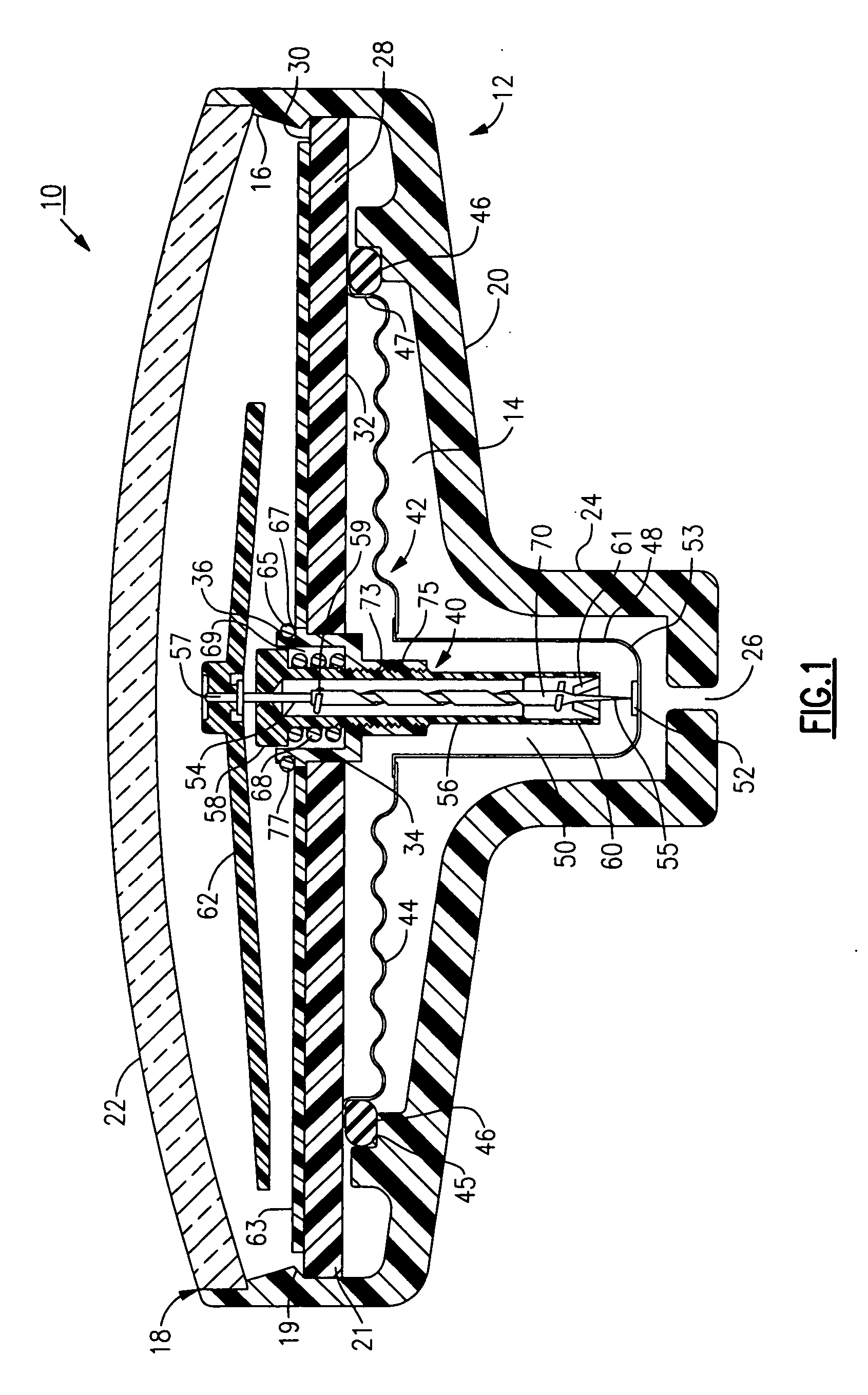
[0074] Referring to FIG. 1, there is shown a blood pressure measuring device or apparatus 10 made in accordance with the invention. The device 10 includes a substantially cylindrical gage housing 12 having an interior cavity 14 defined by a circumferential inner wall 16, an open top end 18, and a bottom end 20. A viewing window or bubble 22, made from glass, plastic, or other suitable transparent material is attached in a known manner to the open top end 18 of the gage housing 12. The bottom end 20 of the gage housing 12 has a diameter which inwardly tapers down to a narrow downwardly extending portion 24 having a bottom opening 26 serving as an inlet port for admitting a fluid. Preferably, the diameter of the narrow extending portion 24 is about one third of the diameter of the major portion of the housing 12, though it will be apparent from the following discussion that this parameter can be suitably varied depending upon the application.
[0075] The interior cavity 14 of the housin...
second embodiment
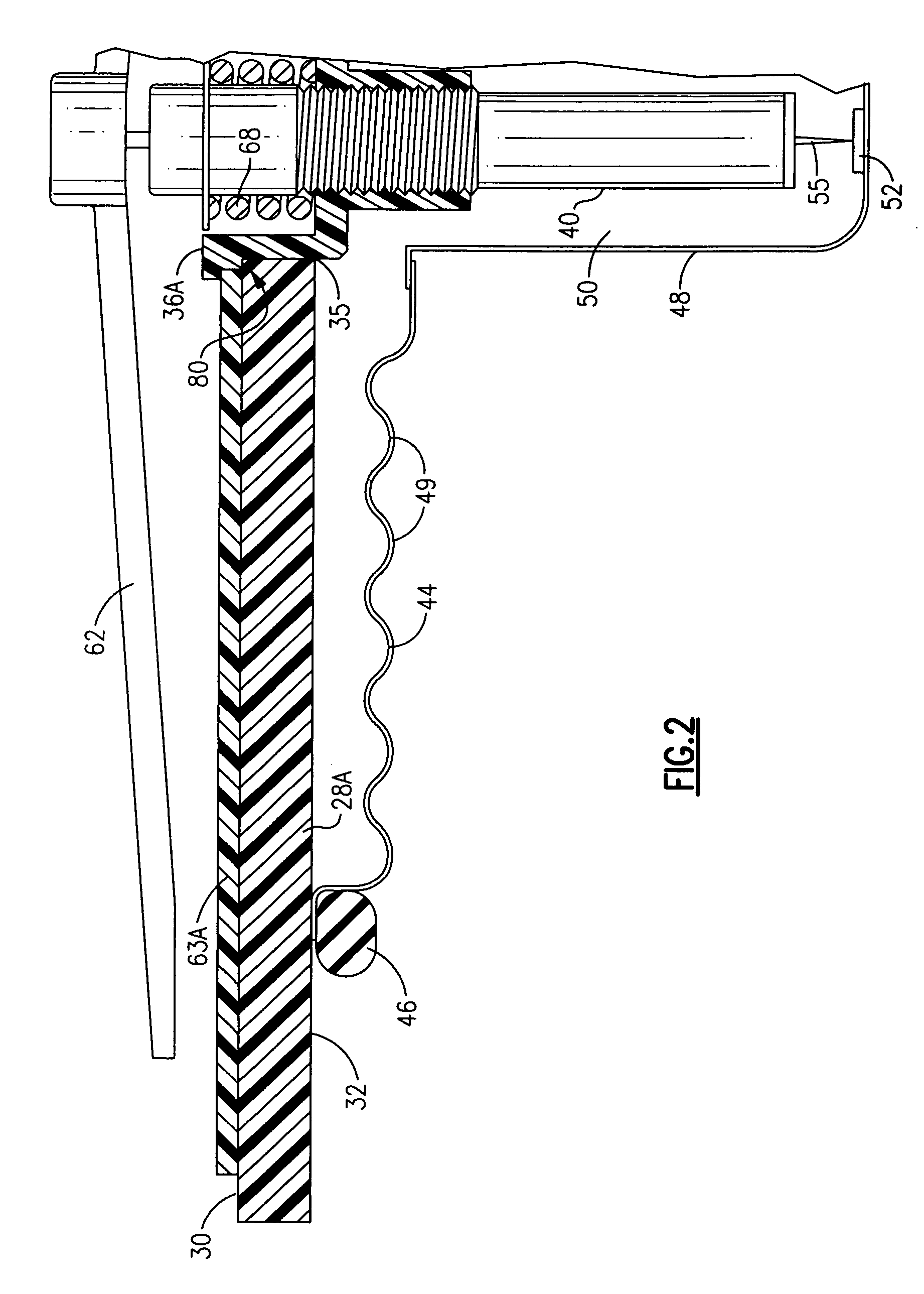
[0086] A housing design in accordance with a second embodiment is illustrated in FIG. 3. Similar parts are herein labeled with the same reference numerals for the sake of clarity. As in the preceding, the device includes a gage housing 12 having an interior cavity 14 sized for retaining a diaphragm assembly 42 that includes a diaphragm 44 having a series of wave-like surfaces 49, as well as a downwardly extending portion or pan 48. The device further includes a substantially horizontally disposed planar support plate 28, the housing 12 further having a downwardly extending narrowed portion 24. A movement mechanism 40 is disposed through a central opening 34 defined in the horizontal support plate 28 such that the bottom end 55 of an axially displaceable shaft 54 of the mechanism is disposed in proximity to a hardened contact surface 52 of the pan 48 of the diaphragm assembly 42. The diaphragm 44 in the meantime is attached, but not sealed, to the bottom facing side 32 of the horizon...
third embodiment
[0089] To further illustrate variations and referring to FIG. 4, a housing 12B made in accordance with the present invention includes a diaphragm 44B, which unlike the preceding embodiments, is a substantially vertical member having an overall width dimension that is considerably narrower than those previously described. As a result, a horizontal support plate is not required, as in the preceding.
[0090] As in the preceding embodiments, an outer edge 47B of the diaphragm 44B is sealed using an O-ring 46B or other sealing member which effectively clamps the outer edge to a shoulder of the a press-fitted sleeve 36B. The movement mechanism 40 is disposed essentially through a center opening in a press-fitted sleeve 36B and threaded into engagement therewith. The majority of the movement mechanism 40 is disposed within the cavity defined by the essentially vertical diaphragm 44B, the particular diaphragm of this embodiment having vertically disposed wave-like surfaces 49B. Adjustments to...
PUM
| Property | Measurement | Unit |
|---|---|---|
| Luminous flux | aaaaa | aaaaa |
| Angle | aaaaa | aaaaa |
| Distance | aaaaa | aaaaa |
Abstract
Description
Claims
Application Information
 - R&D
- Intellectual Property
- Life Sciences
- Materials
- Tech Scout
- Unparalleled Data Quality
- Higher Quality Content
- 60% Fewer Hallucinations
Browse by: Latest US Patents, China's latest patents, Technical Efficacy Thesaurus, Application Domain, Technology Topic, Popular Technical Reports.
© 2025 PatSnap. All rights reserved.Legal|Privacy policy|Modern Slavery Act Transparency Statement|Sitemap|About US| Contact US: help@patsnap.com


