Screw implant and system and method for locking a screw in an implant plate

a screw and implant plate technology, applied in the field of surgical implants, can solve the problems of large thickness, relative complexity of machine and manufacture, etc., and achieve the effect of reducing the number of steps required

Active Publication Date: 2013-09-17
X SPINE SYST
View PDF21 Cites 5 Cited by
  • Summary
  • Abstract
  • Description
  • Claims
  • Application Information

AI Technical Summary

Benefits of technology

[0009]It is, therefore, one object of the invention to provide an integral and compressible screw, system and method having a screw locking mechanism that reduces the number of steps required to attain screw-plate engagement and locking during a surgical procedure.
[0011]Still another object of the invention is to provide a system, method and screw-plate locking mechanism that will permit an improved and simpler plate design and that can, for example, reduce a thickness of the plate or provide other machining and manufacturing advantages.
[0012]In one aspect, one embodiment comprises a plate system comprising a plurality of screws, each of the plurality of screws having a shank and the screw head, a plate having a plurality of apertures for receiving the plurality of screws, respectively, the plate further comprising a plurality of the detent portions associated with the plurality of apertures, respectively, the plurality of detent portions defining a plurality of screw head receiving areas associated with the plurality of apertures, respectively, for receiving at least a portion of the screw head after the screw is screwed into bone, the at least a portion of the screw head being adapted to be compressible when the screw is screwed into bone and expandable so that it can be received in at least one of the at least one of the plurality of screw head receiving areas, the at least a portion of the screw head cooperating with at least one of the plurality of detent portions to restrict or prevent the screw from withdrawing from the plate.
[0013]In another aspect, another embodiment comprises a method for locking a plurality of screws in a plate and preventing them from withdrawing from the plate, each of the plurality of screws comprising a screw head, the method comprising the steps of providing the plate, the plate having a plurality of apertures and a plurality of receiving areas associated with the plurality of apertures, respectively, providing each screw head with a compressible portion, the compressible portion being resilient and compressible when the screw is screwed into bone and expandable so that the compressible portion can expand and be received in at least one of the plurality of receiving areas, the compressible portion of the screw head of each of the plurality of screws cooperating with at least one of the plurality of receiving areas to which it is associated and preventing the screw from withdrawing from the plate.

Problems solved by technology

One drawback of the plates and screw systems of the past is that they were relatively complicated to machine and manufacture and oftentimes required a large thickness in order to provide enough material that will permit the plate to be machined to provide the integral arms and locks.

Method used


Image

  • Screw implant and system and method for locking a screw in an implant plate
  • Screw implant and system and method for locking a screw in an implant plate
  • Screw implant and system and method for locking a screw in an implant plate

Examples


Embodiment Construction

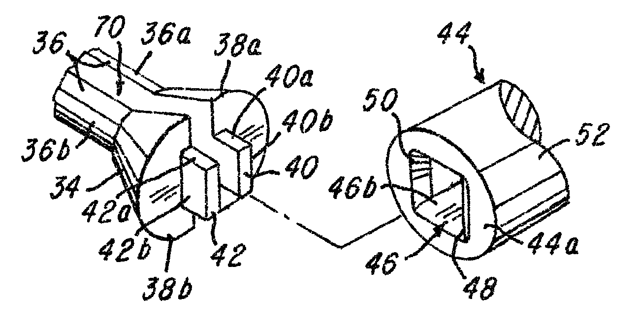
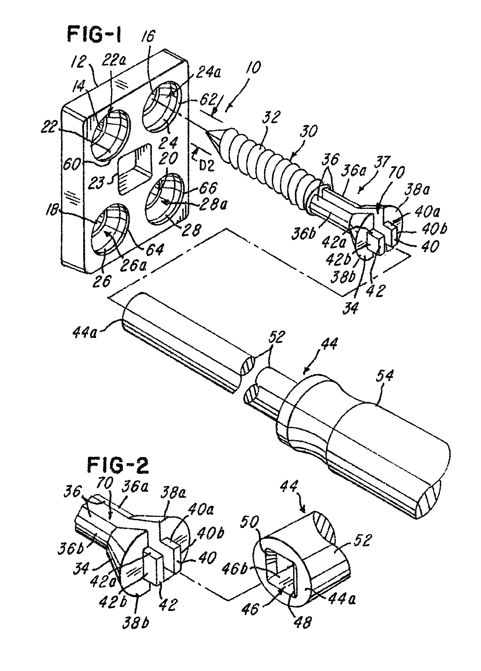
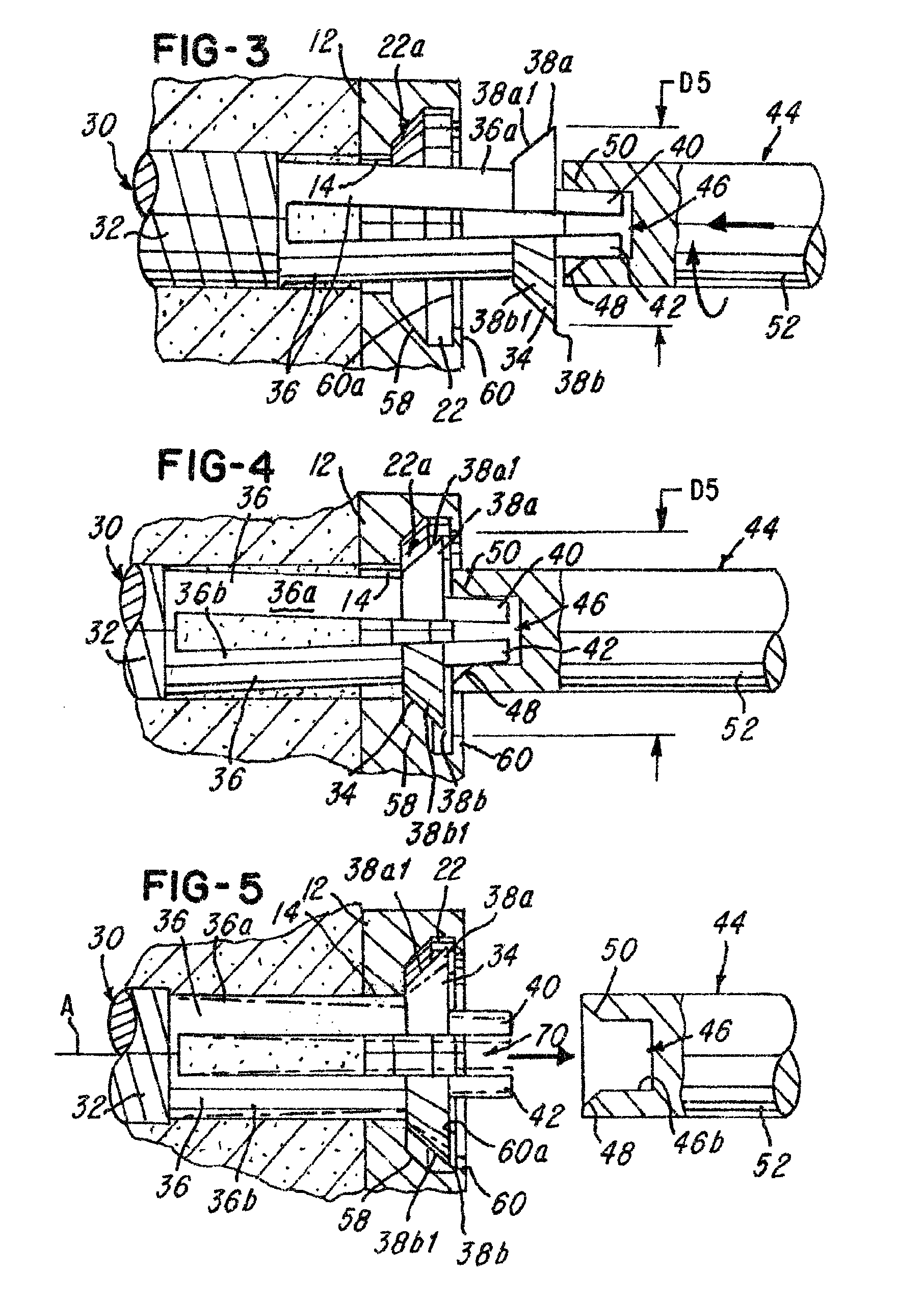
[0030]Referring now to FIGS. 1-14, a system 10 and tool-actuated locking screw mechanism and locking method are shown. The system 10 comprises a plate 12 having a plurality of apertures 14, 16, 18 and 20. The plate 12 may comprise more or fewer apertures if desired and may comprise at least one or a plurality of windows 23 for viewing a graft area (not shown) between two vertebrae to be fused together in a manner conventionally known.

[0031]The plurality of apertures 14-20 each comprise an undercut or interior and generally U-shaped wall 22, 24, 26 and 28, respectively, that define a plurality of receiving areas, apertures, undercuts or continuous undercuts 22a, 24a, 26a and 28a whose purpose and function will be described later herein. For ease of illustration, a sectional fragmentary view of the receiving area 22a is shown and described later herein relative to FIG. 6.

[0032]The system 10 comprises at least one or a plurality of screws 30 for securing the plate 12 to at least one or...


PUM


Abstract

A plate system and method comprising a plate and a screw having an integral resilient lock. The screw comprises a head that has a portion that is adapted to be compressible as it is screwed into bone using a tool. After the screw head is received in the plate and the tool is removed therefrom, the screw head decompresses or expands into a locking or receiving area, thereby locking the screw in the plate. The plate is adapted to have at least one or a plurality of detents or lips for cooperating with at least a portion of the screw head to retain the screw in the plate and prevent it from withdrawing therefrom.

Description

BACKGROUND OF THE INVENTION[0001]1. Field of the Invention[0002]This invention relates to surgical implants and, more particularly, it relates to a surgical implant plate and a screw having a screw head having at least a portion that is compressible when a tool, such as a screw driver, engages and compresses the portion of the screw head so that it can be received in the plate. Thereafter, the screw head can expand or decompress in order to lock the screw in the plate upon retraction or dismounting of the tool from the screw head.[0003]2. Description of the Related Art[0004]In the past, various types of implant plates and screw locking mechanisms have been proposed. For example, several surgical implant devices and methods are shown in U.S. Pat. Nos. 4,488,543; 5,192,327; 5,261,911; 5,549,612; 5,713,899; 5,776,196; 6,136,002; 6,159,245; 6,224,602; 6,258,089; 6,261,586; 6,264,655; 6,306,136; 6,328,738; 6,361,537; and 6,592,586. Some or all of these devices have improved the success r...

Claims


Application Information

Patent Timeline
Patent Type & Authority Patents(United States)
IPC IPC(8): A61B17/80
CPCA61B17/8052A61B17/8615A61B17/888
Inventor KIRSCHMAN, DAVID LOUIS
Owner X SPINE SYST
Why Eureka
Try Eureka