Simulation and correction of mask shadowing effect

a mask and shadowing technology, applied in the field of lithography, can solve the problems of mask shadowing effect, inability of euv lithography to use refractive optical elements, and inability to work well with complicated geometric patterns

Active Publication Date: 2013-09-17
SIEMENS PROD LIFECYCLE MANAGEMENT SOFTWARE INC
View PDF2 Cites 4 Cited by
  • Summary
  • Abstract
  • Description
  • Claims
  • Application Information

AI Technical Summary

Problems solved by technology

Unlike deep ultraviolet (DUV) lithography systems such as the 193 nm system, EUV lithography systems cannot use refractive optical elements because of strong material absorption at the EUV wavelength.
The combination of non-telecentricity at the mask plane and mask topography cause a unique problem for the EUV lithography—the mask shadowing effect.
Moreover, most rule-based compensation methods are empirically developed with simple Manhattan patterns and thus do not work well with complicated geometric patterns.
They are, however, computationally expensive and thus impractical in many applications.

Method used


Image

  • Simulation and correction of mask shadowing effect
  • Simulation and correction of mask shadowing effect
  • Simulation and correction of mask shadowing effect

Examples


Embodiment Construction

[0016]General Considerations

[0017]Various aspects of the present invention relate to modeling and / or correcting flare effects in lithography. In the following description, numerous details are set forth for the purpose of explanation. However, one of ordinary skill in the art will realize that the invention may be practiced without the use of these specific details. In other instances, well-known features have not been described in details to avoid obscuring the present invention.

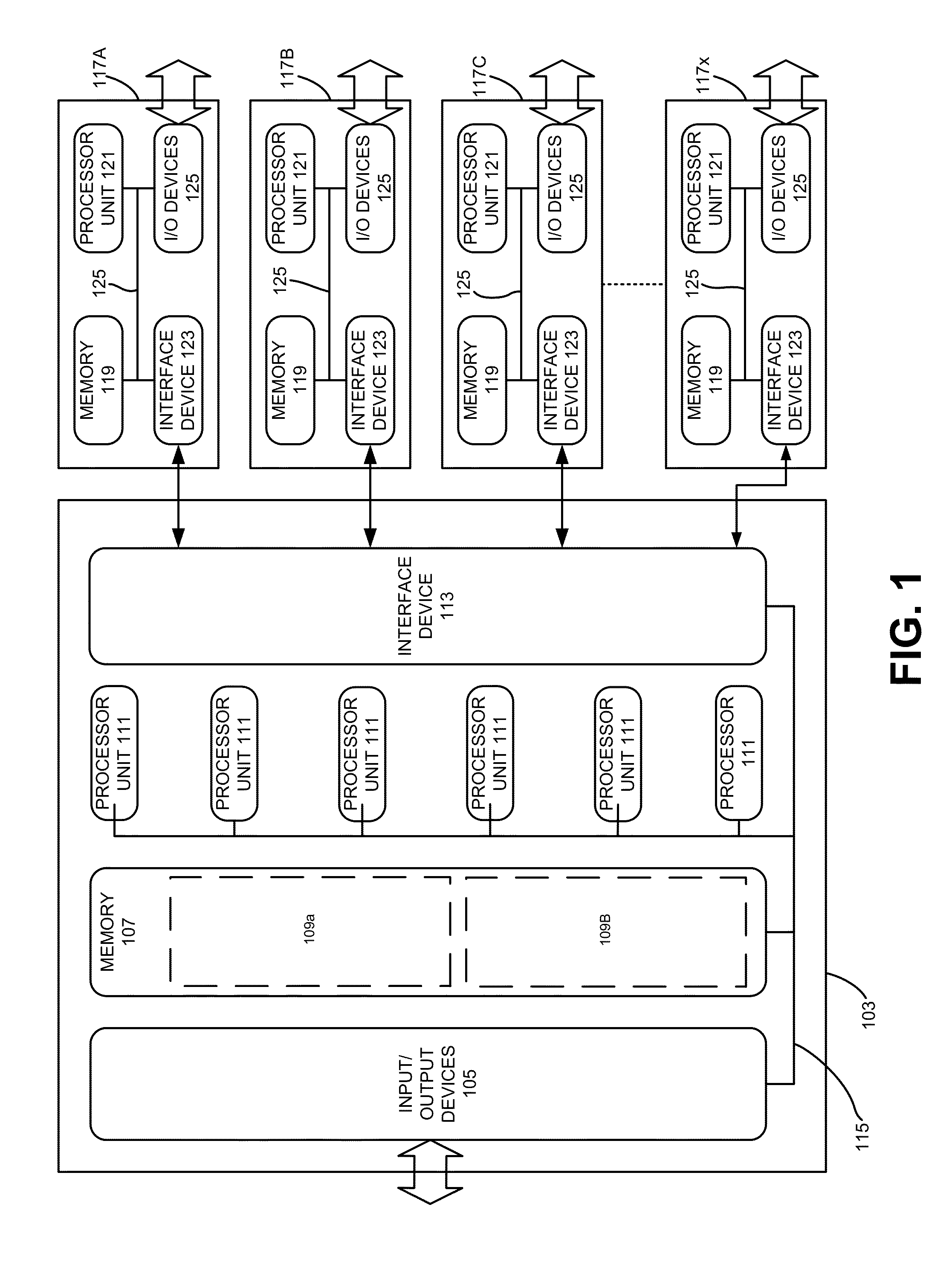
[0018]Some of the techniques described herein can be implemented in software instructions stored on a computer-readable medium, software instructions executed on a computer, or some combination of both. Some of the disclosed techniques, for example, can be implemented as part of an electronic design automation (EDA) tool. Such methods can be executed on a single computer or on networked computers.

[0019]Although the operations of the disclosed methods are described in a particular sequential order for conven...


PUM


Abstract

Disclosed are techniques for simulating and correcting the mask shadowing effect using the domain decomposition method (DDM). According to various implementations of the invention, DDM signals for an extreme ultraviolet (EUV) lithography mask are determined for a plurality of azimuthal angles of illumination. Base on the DDM signals, one or more layout designs for making the mask may be analyzed and / or modified.

Description

FIELD OF THE INVENTION[0001]The present invention relates to the field of lithography. Various implementations of the invention may be useful for simulating and correcting the mask shadowing effect.BACKGROUND OF THE INVENTION[0002]Extreme ultraviolet (EUV) lithography is a leading candidate for the next-generation lithographic solution. The current optical irradiation wavelength for EUV lithography is 13.5 nm. The prototypes operational in the field have demonstrated the feasibility of fabricating 32- and 22-nm node devices. Unlike deep ultraviolet (DUV) lithography systems such as the 193 nm system, EUV lithography systems cannot use refractive optical elements because of strong material absorption at the EUV wavelength. Instead, reflective optical elements such as mirrors are needed. EUV masks also need to work in a reflective mode.[0003]A typical EUV projection printing system includes multiple mirrors. At the mask plane, the chief ray is off-axis by roughly 6 degrees but is perp...

Claims


Application Information

Patent Timeline
Patent Type & Authority Patents(United States)
IPC IPC(8): G06F17/50
CPCG03F7/70433G03F1/70G03F1/22
Inventor WORD, JAMES CADAM, KONSTANTINOS GLAM, MICHAELKOMIRENKO, SERGIY
Owner SIEMENS PROD LIFECYCLE MANAGEMENT SOFTWARE INC
Why Eureka
Try Eureka