Wire grip

a wire grip and wire technology, applied in the field of wire grips, can solve the problems of decreasing the life of the wire grip, damage to the wire grip, and the inefficiency of the conventional wire grip, and achieve the effect of excellent workability

Active Publication Date: 2013-09-24
NAGAKI SEIKI CO LTD
View PDF22 Cites 17 Cited by
  • Summary
  • Abstract
  • Description
  • Claims
  • Application Information

AI Technical Summary

Benefits of technology

[0007]In view of problems described above, the problems to be solved by the invention are to provide the wire grip which has excellent workability for bracing the wire and can grip the linear object for bracing the wire without applying any excessive load to the linear object.
[0010]According to the invention associated with claim 1, the wire grip comprises a stationary-side wire gripping portion provided with the body and having a substantially straight front shape, and a movable-side wire gripping portion arranged to face the stationary-side wire gripping portion and set movable back and forth with respect to the stationary-side wire gripping portion, whereby the linear object can be gripped between the stationary-side wire gripping portion and the movable-side wire gripping portion, wherein the first action portion for moving the movable-side wire gripping portion back and forth and the second action portion connected to the first action portion by the connecting rod are turnably attached at their individual ends to the body, wherein the other end of the first action portion and the other end of the second action portion are turnably attached to one end of the connection rod and an intermediate portion of the connection rod, respectively, wherein the other end of the connecting rod is pulled substantially parallel to the stationary-side wire gripping portion and the movable-side wire gripping portion so that the connecting rod, the second action portion and the first action portion are linked to act to move the movable-side wire gripping portion forward with respect to the stationary-side wire gripping portion, thereby allowing the movable-side wire gripping portion to move back and forth without bringing a moment to the wire grip. Thus, excessive load is less applied to the linear object which is gripped between the stationary-side wire gripping portion and the movable-side wire gripping portion. Therefore, it is less likely that the linear object may curve again and again and be damaged. In addition, since the wire grip can activate the movable-side wire gripping portion to grip the linear object by only hanging the stationary-side wire gripping portion on the linear object and pulling the pulling portion, A worker can easily operate the wire grip from the front side of the wire grip without moving, thus the wire grip is also excellent in workability.
[0011]According to the invention associated with claim 2, the other end of the connecting rod can pull the connecting rod in a close position to the linear object because it is located in the vicinity of the extension line of the movable-side wire gripping portion. Therefore, the moment is less brought to the wire grip and no excessive load is applied to the linear object.

Problems solved by technology

However, most of the conventional wire grips have problems of working inefficiency.
If the linear object W curves again and again, it leads to problems such that the life of the wire grip decreases and the wire grip can be damaged.

Method used


Image

  • Wire grip
  • Wire grip
  • Wire grip

Examples


Embodiment Construction

[0017]Referring to the drawings, preferred embodiments of the wire grip associated with the invention are described below.

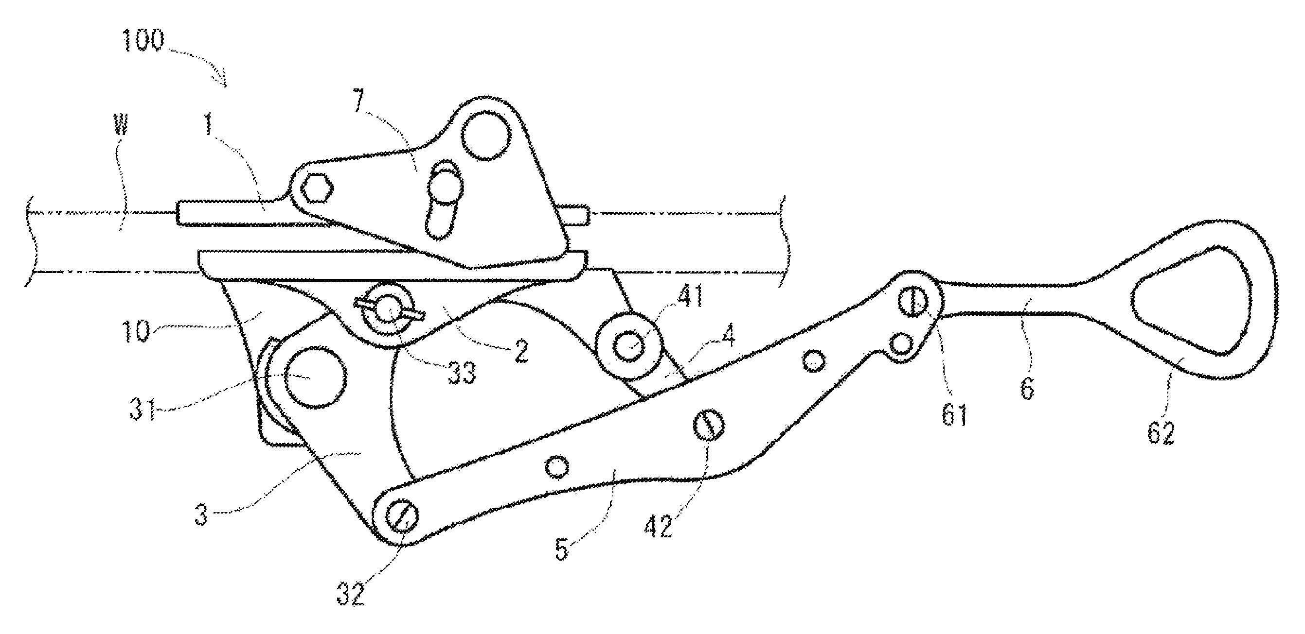
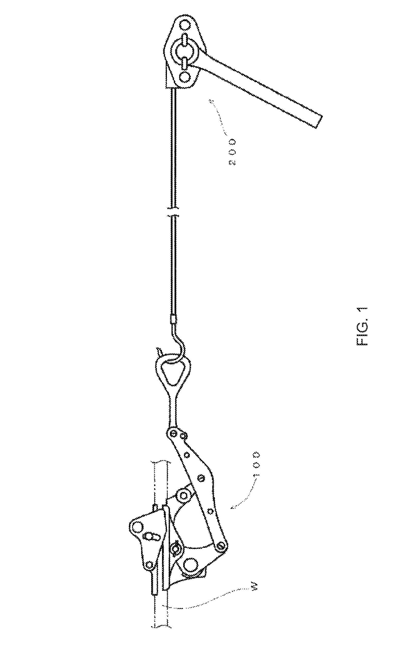
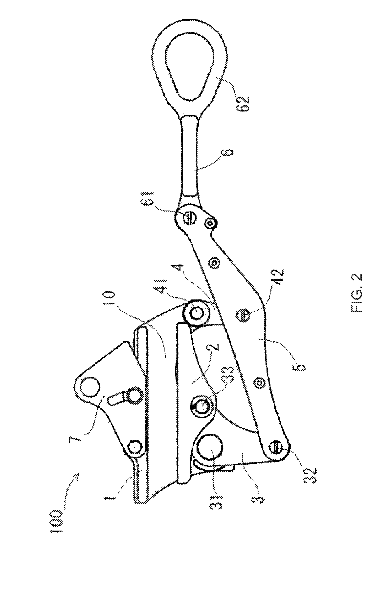
[0018]FIG. 1 illustrates a general example for using a wire grip 100 associated with the invention. Additionally, the front side of the sheets in FIGS. 1, 2, and 4 is considered to be the front side of the wire grip and the directions of top, bottom, left, and right of the sheets in FIGS. 1, 2, and 4 are considered to be the upside, downside, left-side, and right-side of the wire grip herein, respectively. However those directions of the wire grip associated with the invention may be different from those shown in the drawings when the wire grip is used.

[0019]As shown in FIG. 1, the wire grip 100 associated with the invention is connected with the wire puller 200 and used for bracing the wire. In particular, it is used for gripping the linear object W in applying tension by pulling the linear object W such as an elevator wire and an electric wire, i.e. an electric...


PUM


Abstract

A wire grip comprising a stationary-side gripping portion provided with a body and having a substantially straight front shape, and a movable-side wire gripping portion arranged to face the stationary-side wire gripping portion and set movable back and forth with respect to the stationary-side wire gripping portion, whereby the linear object can be gripped between the stationary-side wire gripping portion and the movable-side wire gripping portion, wherein a first action portion for moving the movable-side wire gripping portion back and forth and a second action portion connected to the first action portion by a connecting rod are turnably attached at their individual ends to the body, wherein the other end of the first action portion and the other end of the second action portion are turnably attached to one end of the connection rod and an intermediate portion of the connection rod, respectively, wherein the other end of the connecting rod is pulled substantially parallel to the stationary-side wire gripping portion and the movable-side wire gripping portion so that the connecting rod, the second action portion and the first action portion are linked to act to move the movable-side wire gripping portion forward with respect to the stationary-side wire gripping portion.

Description

TECHNICAL FIELD[0001]The present invention relates to a wire grip used for gripping a linear object such as an electric wire, i.e. an electric power wire and a communication wire and an elevator wire to brace the linear object.BACKGROUND OF THE INVENTION[0002]Conventionally, for bracing the wire in an electric wire construction, a wire grip that grips the electric wire is used to pull the electric wire by a wire puller.[0003]However, most of the conventional wire grips have problems of working inefficiency. For example a worker must move during a step of inserting a linear object (an electric wire) and a step of fixing the linear object by a grip member of the wire grip. Therefore, the wire grips have been required to improve their efficiency when they are used to brace wires in a dangerous situation such as work in high places and in a small area where work space is limited.[0004]Therefore, the wire grip 500 described as follows has been suggested and introduced (see The Patent Doc...

Claims


Application Information

Patent Timeline
Patent Type & Authority Patents(United States)
IPC IPC(8): B66F1/00A62B35/04D06F53/00F16G11/10B63B35/03B65H59/00E21C29/16H02G1/08
CPCB25B25/00H02G1/04H02G1/00Y10T24/394F16B2/18
Inventor IWAMA, TAMOTSU
Owner NAGAKI SEIKI CO LTD
Why Eureka
Try Eureka