
Fluid turbine

a technology of flue gas turbines and turbines, which is applied in the direction of electric generator control, renewable energy generation, greenhouse gas reduction, etc., can solve the problems of low power production efficiency, insufficient utilization, inefficiency, etc., and achieve the effect of economic efficiency of operation, simple design and very short tim

Inactive Publication Date: 2013-09-24
CZECH TECHN UNIV & PRAGUE FACULTY OF CIVIL ENG
View PDF17 Cites 1 Cited by
  • Summary
  • Abstract
  • Description
  • Claims
  • Application Information

AI Technical Summary

Benefits of technology

The invention is about a small hydraulic power generator that can be used to capture and transform energy from moving fluids, such as water, for example for power generation in industrial plants or for backup power sources. The technical effects of the invention are that it is simple and efficient in its operation, can be easily installed and maintained, and can provide a sustainable and cost-effective solution for generating power. It can also be used as a backup source for short-term needs and can be activated quickly. The invention is suitable for various industrial applications and can be used in conjunction with other micro-properties of potential energy from renewable sources of water and other fluids.

Problems solved by technology

The fundamental disadvantages of the turbines mentioned briefly above is that they have to be fitted with a transmission that transmits the turbine's mechanical output to a power generator.
If they are not fitted with a transmission and the rotor and the stator of the rolling turbine constitute a carrying generator, power production has a low efficiency.
Their utilization is, however, still absolutely insufficient and inefficient.

Method used


Image

  • Fluid turbine
  • Fluid turbine
  • Fluid turbine

Examples


Embodiment Construction

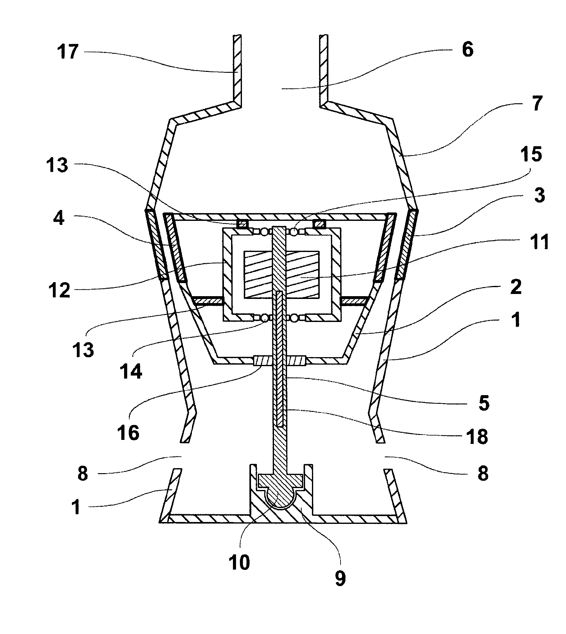
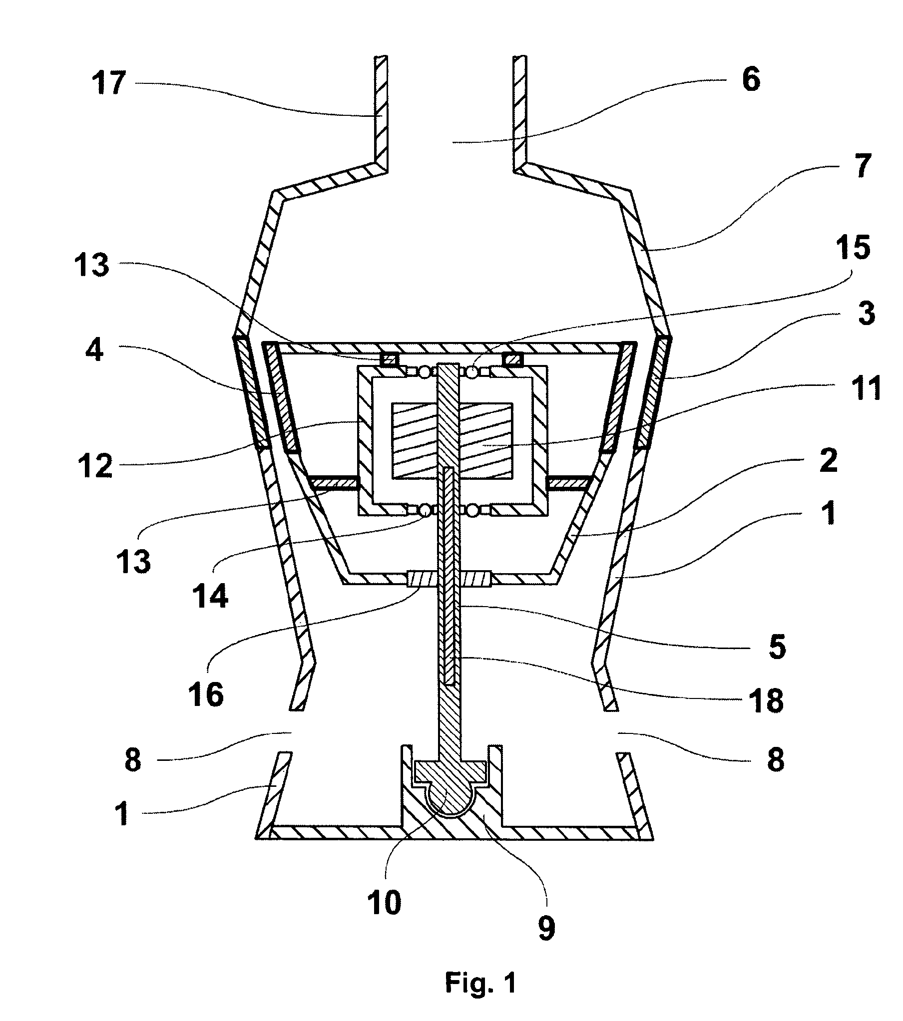
[0015]One of the specific embodiments of the fluid turbine as specified in the invention is shown schematically in FIG. 1.

[0016]The fluid turbine comprises stator 1, which consists, in the direction of fluid supply, of or comprises a confusor 122 mm long and a diffuser 62 mm long attached to it, the diffuser being closed with clamp 9 of clamping mechanism 10. The biggest internal diameter of the confusor is 160 mm and the smaller diameter 109 mm. The smallest internal diameter of the diffuser is 109 mm and the biggest diameter 138 mm. A part of stator 1, in the shape of the confusor, has hydraulic channels 3 on the side of the biggest confusor diameter, the channels being oriented along the longitudinal axis of stator 1 and their length being 43 mm. Using shaft 5, rolling rotor 2 is placed inside stator 1, in the area of the confusor; the rolling rotor having the shape of a blunted cone, the biggest diameter 144 mm, the smallest diameter 85 mm and its length 95 mm. On the side of th...


PUM


Abstract

A fluid turbine includes stator fitted with fluid inlet and outlet, and a rolling rotor installed inside the confusor part of the stator at one end of a shaft, with the other end fixed in a clamp of a clamping mechanism on the stator. The shaft of the rolling rotor is fixed in the clamp of the clamping mechanism non-rotationally with the possibility of angular deflection in all directions. A generator is connected to the shaft.

Description

BACKGROUND AND SUMMARY[0001]This technical solution involves fluid turbines in the shape of rolling fluid machines comprising a cylindrical or conical stator, in which a rotor of an axially symmetrical shape is seated on the shaft. The rotor touches a stator and can circulate around its internal wall.[0002]Fluid turbines with the rolling principle are generally known, comprising a stator, usually in the shape of a confusor, while the rotor has an axially symmetrical shape, very often a hemisphere or a cone. For example based on Czech patent No. 284483 with the title Rolling Fluid Machine, and European patent No. EP1015760 B1 with the title Rolling Fluid Machine, a water turbine is known, comprising a fluid reservoir with an inlet and at least one outlet nozzle, with a rolling rotor of an axially symmetrical shape placed on a holding device near the outlet nozzle. This machine can operate as a water turbine, when the water flowing around the rotor deflects it towards the internal sid...

Claims


Application Information

Patent Timeline
Patent Type & Authority Patents(United States)
IPC IPC(8): F01D3/00
CPCF03B3/04F03B5/00F03B11/00F03B11/066F03B13/00Y02E10/20Y02E10/223Y02E10/226
Inventor SEDLACEK, MIROSLAVBERAN, VACLAVNOVAK, JIRI
Owner CZECH TECHN UNIV & PRAGUE FACULTY OF CIVIL ENG
Learn More