[0002]Fluid turbines with the rolling principle are generally known, comprising a stator, usually in the shape of a confusor, while the rotor has an axially symmetrical shape, very often a hemisphere or a cone. For example based on Czech patent No. 284483 with the title Rolling Fluid
Machine, and European patent No. EP1015760 B1 with the title Rolling Fluid Machine, a
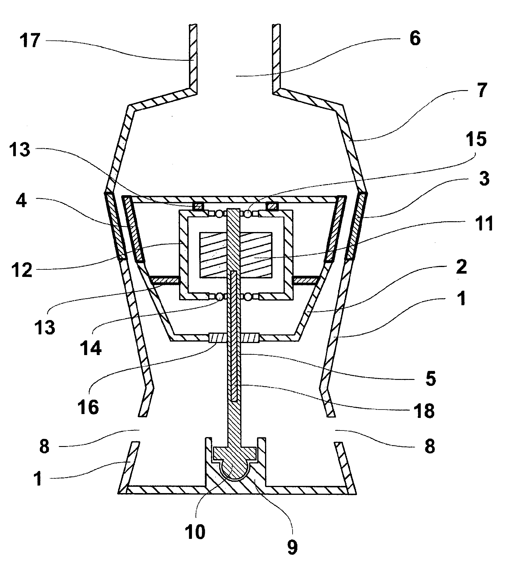
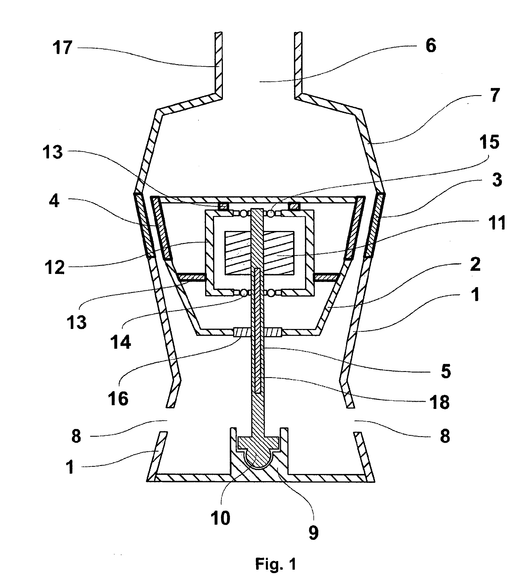
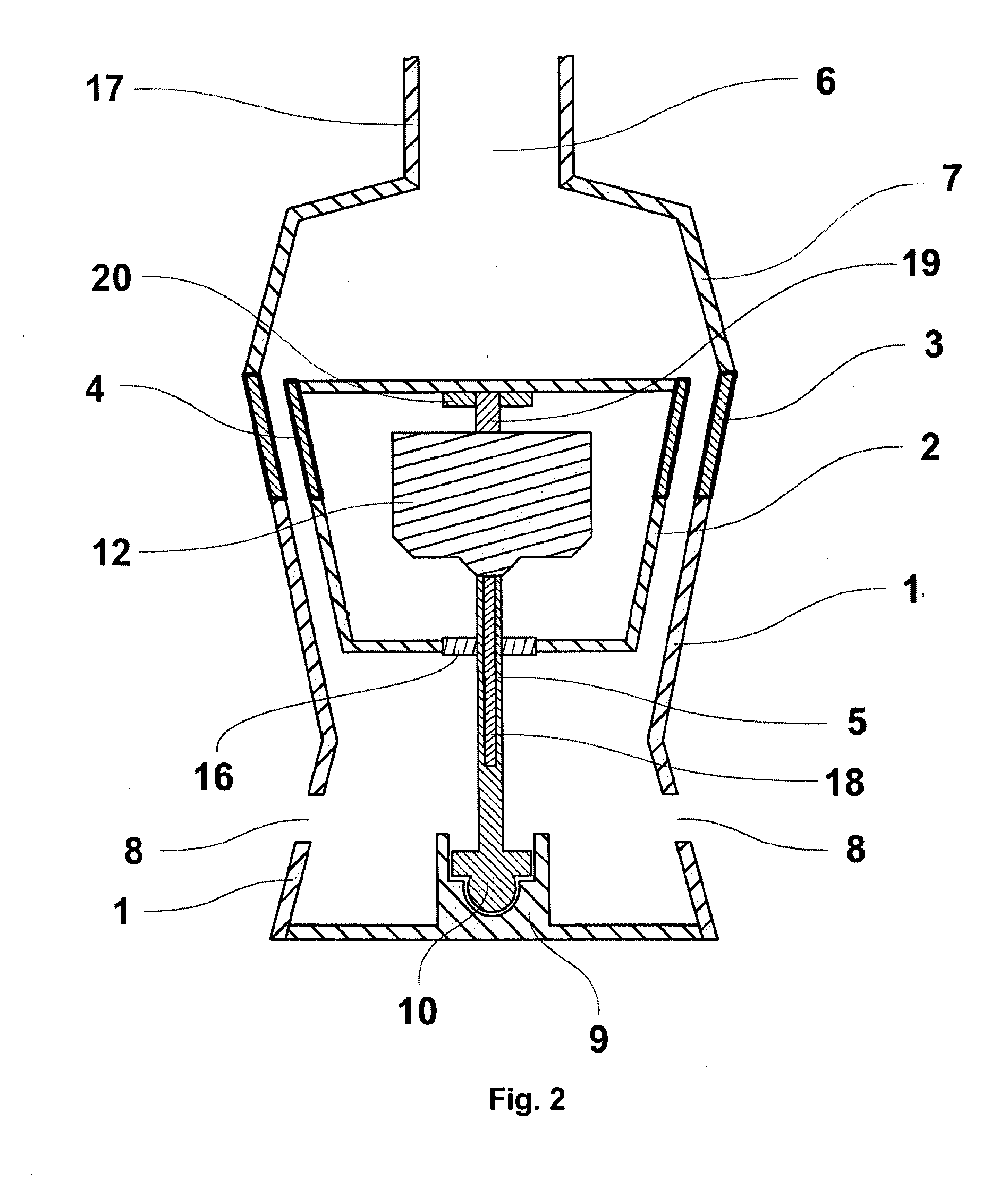
water turbine is known, comprising a fluid reservoir with an inlet and at least one outlet
nozzle, with a rolling rotor of an axially symmetrical shape placed on a holding device near the outlet nozzle. This
machine can operate as a water turbine, when the water flowing around the rotor deflects it towards the internal side of the outlet nozzle and starts rolling it in the outlet nozzle-stator. The solution of the rolling fluid motor in the design patented by Czech patent No. 7606 with the title
Hydraulic Motor and European patent No. EP1082538 B1 with the title
Hydraulic Motor can be used to produce energy. Likewise, the solution under Czech patent No. 294708 with the title Rolling Fluid
Turbine shows a water motor of the rolling type, with hydraulic channels arranged in the places of mutual contact between the rotor and the stator; these channels also act as a geared transmission, preventing rotor slippage inside the stator.
[0004]It is desirable to adjust the rolling turbine to improve the efficiency of its function, i.e. to make sure that the transformation of the obtained
mechanical energy to power does not require any geared transmissions.
[0008]Practice has confirmed that if the difference in the diameters of the rolling rotor and the stator is at least 1 cm, the water used can be polluted by soft
biological materials with the size of several centimeters, such as residues of grass, leaves, clusters of
algae etc. These residues do not affect the turbine'
s function and pass through it, leaving it in a partly crushed condition.
[0010]From an economic point of view, the industrial application of the presented solution consists of or comprises especially in specific forms of production and utilization of the generated power. Very small renewable sources of hydraulic energy can be very important in real economy because the frequency of water micro-sources is very high in certain regions. Their utilization is, however, still absolutely insufficient and inefficient. From the point of view of the presented solution, micro-sources also include all pumping equipment in industrial plants, public facilities, housing projects, where fluids are circulating. In case of a
closed circuit of
power handling, where the generated power is consumed in the place of its production, the technical solution as specified in this invention can yield major
economic benefits. When the costs of maintenance of the equipment are deducted, the benefits will correspond with the saved payments for power supply from the public distribution network. The generated power is first accumulated, and later used as needed. It is not provided to other entities for any fee and is used exclusively for consumption in the place of its production. Its industrial applications include telemetric measurements of
industrial systems, linked for example to safety, registration and failure conditions and other functions for applications where connection to the public distribution network is expensive and does not meet the functional needs. The micro-source can perform the function of a
backup source for short-term needs and can be activated within a very short period of time.
[0011]The presented solution therefore seems to be
usable industrially in the field of
sustainable development and the determining economic and environmental context. As implied above, no fields of power generation can be excluded from
sustainable development in advance. It is therefore necessary to count on the use of micro-properties of
potential energy from renewable sources of water and other fluids. The fluid turbine as specified in this invention can become another tool for specific exploitation thanks to its simple design and economic efficiency of its operation as well as the return on investments.

