Driving system of permanent magnet synchronous motor

a synchronous motor and driving system technology, applied in the direction of electric controllers, electronic commutators, dynamo-electric converter control, etc., can solve the problems of large estimation error, inability to accurately calculate the disclosed current change quantity, and large position estimation error, so as to improve the starting torque of the driven motor, improve the accuracy of estimation, and reduce the effect of noise caused by a pulsating current at the time of initial position estimation

Active Publication Date: 2013-09-24
HITACHI IND EQUIP SYST CO LTD
View PDF11 Cites 20 Cited by
  • Summary
  • Abstract
  • Description
  • Claims
  • Application Information

AI Technical Summary

Benefits of technology

[0011]For improving the position estimation precision in the method disclosed in JP-A-2007-174721, it is necessary to increase the number of determinant values obtained by referring to the magnification α and the current characteristics. Increasing the number of determinant values is equivalent to making the decision range finer, and it is considered that false decisions become apt to occur in the magnetic pole discrimination due to the influence of noise or the like. For reducing false decisions, it becomes necessary to apply a high voltage to cause stronger magnetic saturation and increase the motor current to widen intervals between determinant value boundaries. As a result, however, there is a problem that noise caused by the motor becomes great.
[0013]Another object of the present invention is to provide a control apparatus and a control method of a synchronous motor which makes it possible to estimate magnetic pole positions with high precision on the basis of three-phase detected currents without requiring adjustment work such as grasp current characteristics of the driven motor beforehand and studying the determinant values.
[0035]The present invention brings about an effect of improving the estimation precision by extracting current characteristics depending upon permanent magnet magnetic pole positions which bring about the same amplitude and conducting initial position estimation, in each of the three phases. Owing to this precision improvement, the present invention brings about an effect of improving the start torque of the driven motor.
[0036]Furthermore, since current characteristics of magnetic saturation of the iron core using the permanent magnet are utilized in the initial position estimation more strictly as compared with the conventional method, the lowest motor current required to satisfy the required value of estimation precision can be further decreased. As a result, noise caused by a pulsating current at the time of initial position estimation can be reduced, resulting in an effect of quietness.

Problems solved by technology

Therefore, the magnetic pole position estimation technique disclosed in JP-A-2006-158101 has a problem that the position estimation error becomes great because three-phase currents detected from the shunt resistor at the time of application to the two orthogonal axes do not have magnetic saturation characteristics of the same condition.
As a matter of fact, the V-phase is different from the W-phase in the number of interlinkage magnetic fluxes, and consequently influences of magnetic saturation are not equal and the disclosed current change quantity calculation method is not accurate.
As a result of them, estimation of the magnetic pole position of the synchronous motor according to the method disclosed in JP-A-2006-158101 brings about a problem that the estimation error becomes great.
Increasing the number of determinant values is equivalent to making the decision range finer, and it is considered that false decisions become apt to occur in the magnetic pole discrimination due to the influence of noise or the like.
As a result, however, there is a problem that noise caused by the motor becomes great.

Method used


Image

  • Driving system of permanent magnet synchronous motor
  • Driving system of permanent magnet synchronous motor
  • Driving system of permanent magnet synchronous motor

Examples


first embodiment

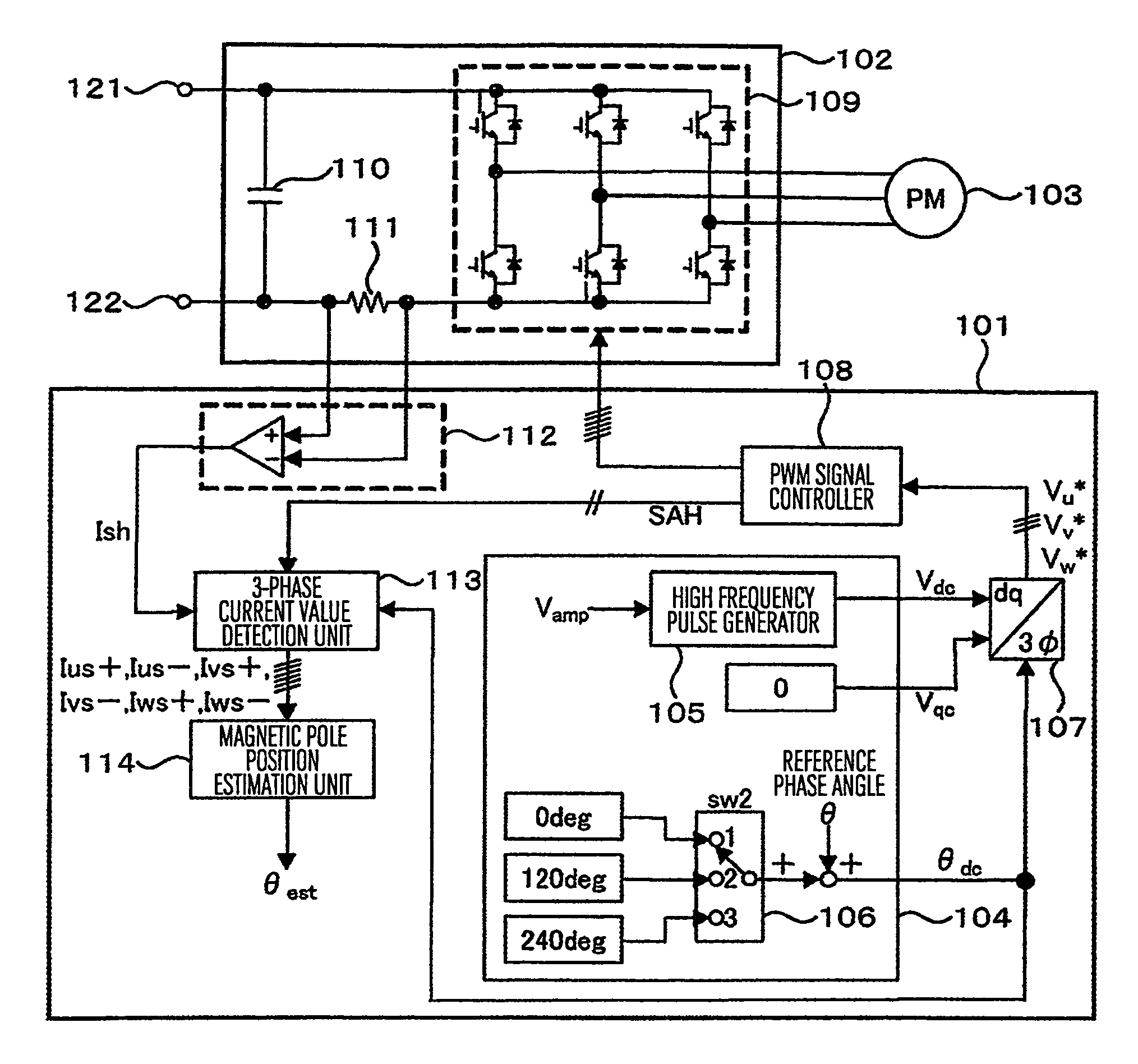
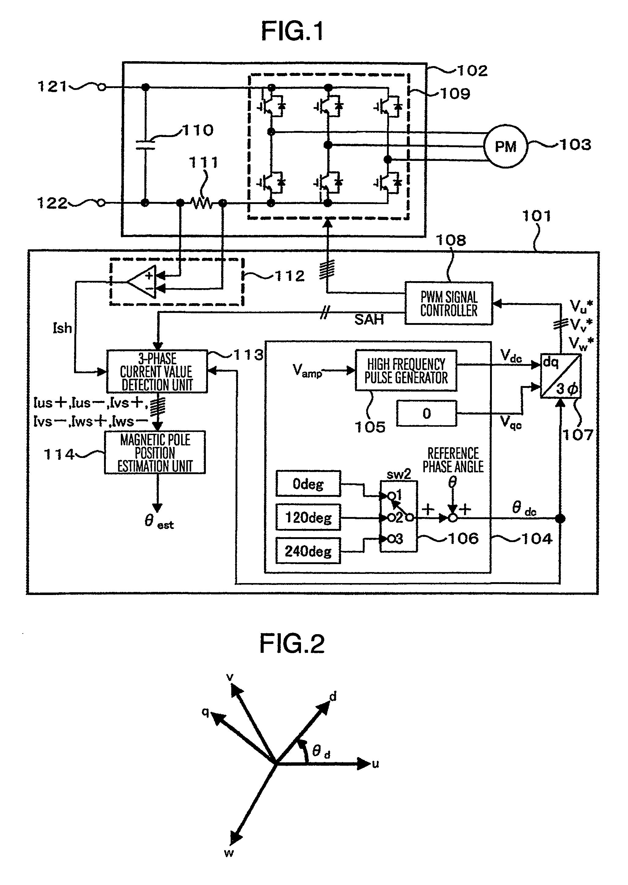
[0077]FIG. 1 is a configuration diagram of a driving system of permanent magnet synchronous motor according to the present invention. The driving system includes a permanent magnet synchronous motor 103 to be controlled, a power converter 102 for driving the permanent magnet synchronous motor 103, and a control apparatus 101 for controlling the power converter 102 and the permanent magnet synchronous motor 103. The control apparatus 101 includes a unit having a dc axis which is a phase axis for applying a high frequency voltage to the permanent magnet synchronous motor 103 and a qc axis perpendicular to the dc axis and providing a voltage command value of a high frequency component on the dc- and qc-axes, and a unit for detecting a current which flows through a DC resistor 111 in the power converter 102. The control apparatus 101 estimates a magnetic pole position in the permanent magnet synchronous motor 103 on the basis of a difference between a positive side change quantity and a...

second embodiment

[0154]In the second embodiment, the trigger signal TRG is generated at timing of the triangular wave PWM carrier signal becoming a wave crest or wave bottom when the value of the status signal STS is 1 or 3. In the operation waveform example, the TRG signal is output at timing of the PWM carrier signal becoming a wave bottom.

[0155]Phase currents are detected at timing of the pulse output of the trigger signal TRG. Black dots (●) in current waveforms shown in (h) and (i) of FIG. 24 indicate sampled current values. In the present embodiment, the phase current detection unit 115 detects only the U-phase Iu and the V-phase current Iv. The W-phase current Iw which cannot be detected directly is calculated from the detected values of the U-phase and the V-phase on the basis of Equation (9).

Iw=−(Iu+Iv)  (9)

[0156]Rhomb marks (⋄) in the current waveform of Iw shown in (j) of FIG. 24 indicate calculated W-phase positive side detected value Iw+ and W-phase negative side detected value Iw−.

[015...

fourth embodiment

[0208]An internal configuration of the three-phase current value detection unit 113″ in the fourth embodiment is shown in FIG. 33. A sampler in the three-phase current value detection unit 113″ samples the detected current Ish at time when the pulse of the trigger signal TRG has become the high level. The trigger signal TRG and sample timing of detected current values utilized for the magnetic pole position estimation are shown in FIG. 32. Black dots (●) in current waveforms shown in FIG. 32(h), (i), (j) and (k) indicate sampled current values. Sampled Ish values are distributed to positive and negative values of respective phase currents on the basis of information of the electric phase angle θdc and the status signal STS. The distribution is conducted according to the following rules.[0209]A sample value of a first point of Ish obtained in response to a TRG signal which is generated when θdc=0 degree and STS=1 is regarded as a U-phase positive side current Iu1+.[0210]A sample valu...


PUM


Abstract

When applying a high frequency voltage which alternates on positive and negative sides to a permanent magnet synchronous motor, a driving system of synchronous motor switches the applied voltage phase by 120 degrees successively and applies resultant voltages to three phases. A pulsating current generated by applying a high frequency voltage is detected at timing of elapse of a predetermined time Δt since an output voltage of at least one phase has changed from a state in which all output voltages of the three phases of a power converter are positive or negative. Current detection is conducted by using a DC resistor or a phase current sensor provided on a DC bus. A magnetic pole estimation unit calculates the rotor magnetic pole position of the permanent magnet synchronous motor on the basis of differences between positive side and negative side change quantities in three-phase currents obtained from detected current values.

Description

BACKGROUND OF THE INVENTION[0001]The present invention relates to control of a synchronous motor which uses a permanent magnet in its field system. In particular, the present invention relates to a control apparatus and a control method which implement the control of the synchronous motor without using a sensor to detect the magnetic pole position of the rotor.[0002]As techniques for controlling the synchronous motor without detecting the magnetic pole position of the rotor, there are techniques disclosed in JP-A-2006-158101 and JP-A-2007-174721.[0003]According to the technique disclosed in JP-A-2006-158101, a minute changes is given to each of voltage commands on a dc axis which is an estimation magnetic pole axis of a synchronous motor and a qc axis perpendicular to the dc axis, and the magnetic pole position of the synchronous motor is directly estimated by utilizing a difference between a positive side current value and a negative side current value of a resultant current pulsat...

Claims


Application Information

Patent Timeline
Patent Type & Authority Patents(United States)
IPC IPC(8): G05B11/28H02P6/18H02P6/06H02P6/08H02P6/182H02P6/28
CPCH02P9/009H02P9/30H02P21/146H02M7/53873H02P6/18H02P21/18
Inventor SAKAI, TOSHIFUMIIWAJI, YOSHITAKASAKAMOTO, KIYOSHITAGUCHI, YOSHIYUKIKANEKO, DAIGO
Owner HITACHI IND EQUIP SYST CO LTD
Why Eureka
Try Eureka