Eureka AIR delivers breakthrough ideas for toughest innovation challenges, trusted by R&D personnel around the world.

Aerostat assembly

a technology of aerostats and components, applied in the direction of lighter-than-air aircraft, instruments, transportation and packaging, etc., can solve the problems of difficult positioning of cameras to maintain picture frames, difficult use of aerostats for aerial photography and surveillance, and little operator control, so as to achieve low energy requirements, easy transportation, and minimal vibration

Inactive Publication Date: 2013-10-01
CAPTURES
View PDF26 Cites 72 Cited by
  • Summary
  • Abstract
  • Description
  • Claims
  • Application Information

AI Technical Summary

Benefits of technology

The patent describes an improved aerostat assembly for aerial photography and surveillance. The assembly allows for precise control over the camera position, is easy to transport, uses smaller amounts of expensive gas, minimizes vibrations for camera equipment, and can operate for longer periods of time over helicopters with low energy requirements. The assembly can also include multiple cameras for increased viewing angles. The balloon in the assembly acts as a lift source, reducing the need for large lift rotors and allowing for greater flights over helicopters. It also prevents the assembly from crashing to the ground in case of failure. The assembly can be tethered to the ground or used in an untethered embodiment.

Problems solved by technology

Using conventional aerostats for aerial photography and surveillance is difficult.
Aerostats allow little operator control.
Positioning the camera to maintain a picture frame is difficult as aerostat position is affected by wind.
The ability to maneuver and rotate an aerostat is limited.
Much operator effort is required to keep the tether line and other aerostat components from blocking or falling into the picture frame.
Additionally, balloons used with conventional aerostats must be very large to provide sufficient lift to raise the aerostat to a desired elevation.
While helicopter-type aircraft offer an improved degree of positional control over conventional aerostats, constant use of rotors transmits vibrations to attached cameras, resulting in impaired image quality.
Constant rotor operation to maintain lift consumes large amounts of energy and limits fight times, limiting the amount of time a camera can maintain a desired aerial picture frame.
If rotors or other mechanical components fail, helicopter control becomes impossible.
The helicopter-type aircraft will crash to the ground, damaging the aircraft and attached camera equipment and risking injury to by-standers.

Method used


Image

  • Aerostat assembly
  • Aerostat assembly
  • Aerostat assembly

Examples


first embodiment

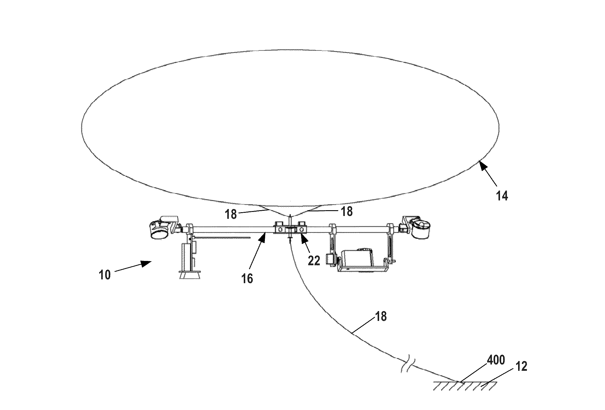
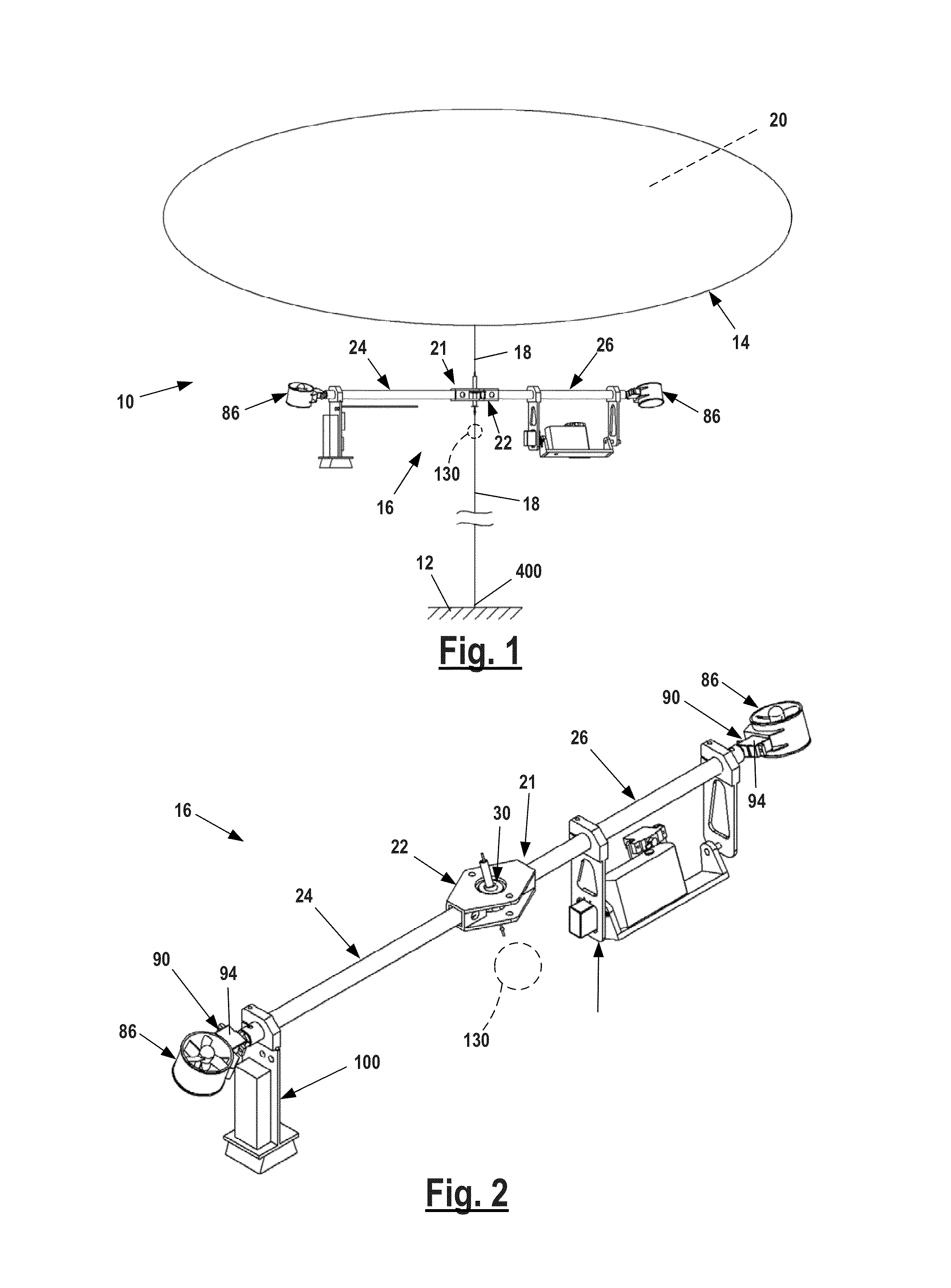
[0037]FIG. 1 is a perspective view of a first embodiment aerostat assembly 10 tethered to ground 12.

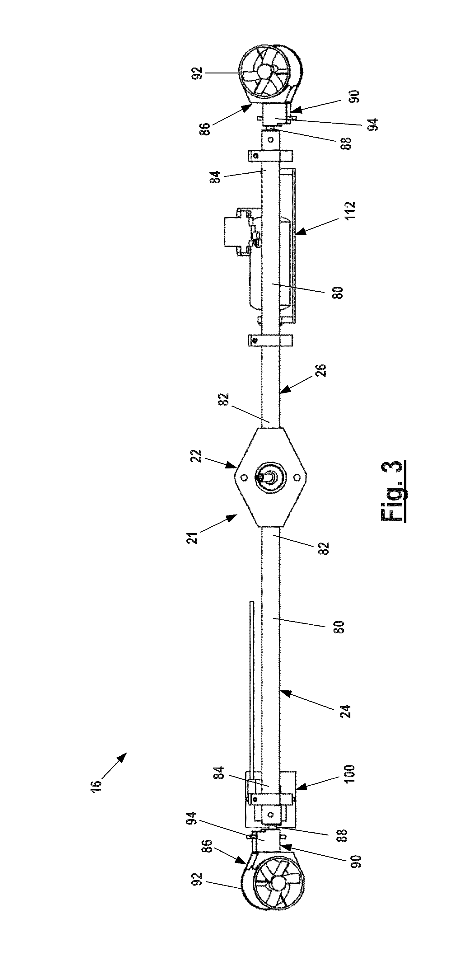
[0038]Assembly 10 is made up of an aerostat balloon 14 jointed to a frame assembly 16 by a tether line 18. Frame assembly 16 hangs freely under balloon 14 and is supported by tether line 18.

[0039]The tether line 18 joining frame assembly 16 to aerostat balloon 14 may be a length of flexible conventional cord or line used to tether aerostat assemblies or may be a short linkage made of metal or other study, inflexible material. If desired, the tether line 18 joining the frame assembly 16 to aerostat balloon 14 may include multiple lines 18 as shown in FIG. 14.

[0040]Aerostat balloon 14 may be any conventionally known balloon used for moored balloons, blimps or other free flying airships. Balloon 14 is filled with a buoyant, lighter-than-air gas 20 that provides lift to assembly 10. If desired, balloon 14 may be a kite-type aerostat that provides aerodynamic lift though an oblate body sha...

second embodiment

[0081]FIGS. 17-22 illustrates a second embodiment aerostat assembly 200.

[0082]Assembly 200 is generally similar to above described assembly 10, made up of an aerostat balloon jointed to a frame assembly 210 by a tether line 212, like tether line 18 described above. Frame assembly 210 hangs freely under the balloon and is supported by tether line 212.

[0083]As shown in FIGS. 17-22 second embodiment aerostat assembly 200 frame assembly 210 has a center support 214 joined to polygonal frame 216 by a number of spars 218.

[0084]Center support 214 is made up of a support plate 220 and pivot assembly 222. Pivot assembly 222 is mounted to plate 220 by a number of fasteners 224. Pivot assembly 222 may be identical to pivot assembly 30 as described above and have a gimbal assembly 226 like gimbal assembly 48. Center support 214 engages tether line 212 in a manner similar or identical to tether line 18 engaging pivot assembly 30 as described above. Support plate 220 has a number of downwardly-ex...


PUM


Abstract

An aerostat assembly, specifically an aerostat assembly including one or more cameras for aerial photography and surveillance. The aerostat assembly includes a frame assembly having a pivot assembly joined to a balloon tether line. Thrusters on the frame allow an operator to maneuver the assembly to desired positions as well as rotate the frame assembly about the pivot assembly.

Description

[0001]This application is a continuation-in-part of my co-pending PCT application for Aerostat Assembly, Application No. PCT / US2010 / 041197 filed Jul. 7, 2010.FIELD OF THE DISCLOSURE[0002]The disclosure relates to aerostat assemblies, in particular, aerostat assemblies having one or more cameras for aerial photography and surveillance.BACKGROUND OF THE DISCLOSURE[0003]It is known to use aerostat aircraft or model helicopter-type aircraft having a mounted camera to capture aerial photographic and video images. Aerostats are aircraft that remain aloft primarily by lift provided by a buoyant balloon and / or by aerodynamic lift provided by the contoured shape of the balloon. Conventional aerostats are moored to the ground by a tether line to prevent escape from the operator. Helicopter-type aircraft, normally either helicopters or multicopters, remain aloft through lift provided by one or more engine driven rotors.[0004]Using conventional aerostats for aerial photography and surveillance ...

Claims


Application Information

Patent Timeline
Patent Type & Authority Patents(United States)
IPC IPC(8): B64B1/50
CPCB64B1/28B64B1/50B64C39/024B64C2201/022B64C2201/042B64C2201/123B64C2201/165G08B13/194B64U10/30B64U50/13B64U20/87B64U2101/31B64U10/60
Inventor CAPPER, HARRY M.
Owner CAPTURES
Why Eureka
Eureka Blog
Learn More