Wiring apparatus

a technology of wiring apparatus and wires, which is applied in the direction of connection contact material, cell components, coupling device connection, etc., can solve the problems of short-circuit between wires, increased apparatus cost, and ineffective compensation of battery pitch, so as to achieve flexible connection angle. , the effect of adjusting the connection angl

Active Publication Date: 2013-10-01
YAZAKI CORP
View PDF8 Cites 18 Cited by
  • Summary
  • Abstract
  • Description
  • Claims
  • Application Information

AI Technical Summary

Benefits of technology

[0018]According to the first aspect, the elongated housing groove for housing the wire therein is divided at one or more pieces and the adjacent end portions of each pair of the adjacent divided pieces of the housing groove are coupled by the U-shaped elastic coupling member. Thus, even if there is a tolerance of the battery pitch, the tolerance can be compensated by the shrink or expansion of the U-shaped elastic coupling member. Accordingly, since a stress is not applied to the voltage detection wire housing portions, the strong voltage detection wire housing portions capable of withstanding for a long term use can be obtained.
[0019]According to the second aspect, each of the wire housing portions is provided therein with a projection, each of which acts to lock and prevent the wire housed in the wire housing portion from being extruded therefrom. Thus, the wire housed within the wire housing portion is prevented from extruding from the housing groove accidentally, so that the wires can be housed stably and so an unexpected accident does not arise.
[0020]According to the third aspect, preferable one of the vertical coupling member and the horizontal coupling member can be selected in view of the circumferential state as the U-shaped elastic coupling member for coupling the adjacent end portions.
[0021]According to the fourth aspect, the wire housing portion is provided at the portion thereof to be coupled to the connector with the hinge portion which is formed to be bent in the W-shape when seen from the direction crossing the wire housing portion. Thus, even if there is the tolerance of the battery pitch as to the batteries or the design error of a distance between the battery and the connector, such the tolerance and the design error can be compensated. Further, since the attachment angle of the connector can be changed, the attachment angle of the connector can be coped flexibly.

Problems solved by technology

Thus, according to the configuration described in Patent Literature 1, since the number of times of using the overcurrent prevention resistor elements increases, the cost of the apparatus increases.
Further, the configuration described in Patent Literature 1 can compensate the positional deviation between the battery and the electronic component provided adjacent to the battery, but can not effectively compensate the tolerance of the battery pitch and the design error of a distance to a PCB assembly attached to the side of a battery module from the battery module.
Thus, since the wires are directly made in contact, there may arise a short-circuit between the wires.
In this case, each of the wires is required to be covered by a protection member such as a corrugate or a tube in order to prevent the short-circuit, which results in the increase of the time and labor.
Further, the wires are bound into the bundle, so that there arises a problem in a point of the maintenance since it is difficult to quickly and accurately recognize as to which one of the wires of the connector side is coupled to which one of the batteries.

Method used


Image

  • Wiring apparatus
  • Wiring apparatus
  • Wiring apparatus

Examples


first embodiment

[0029]

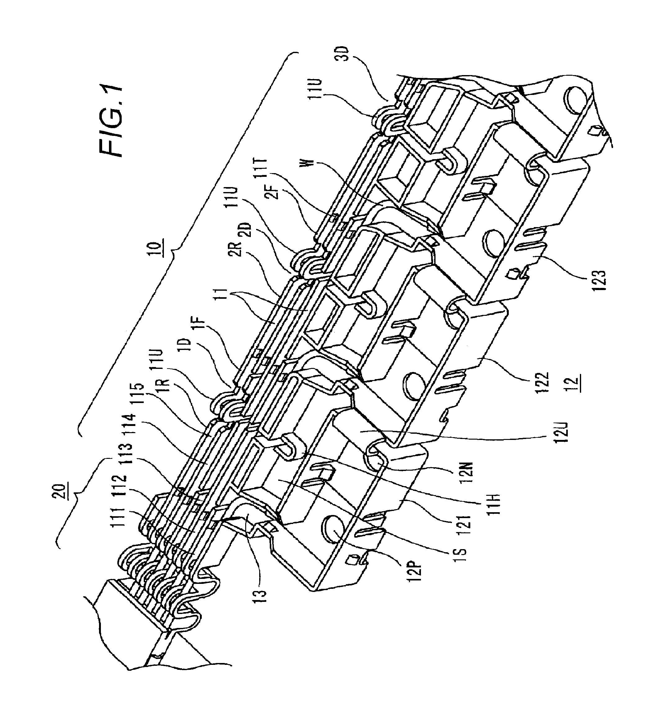
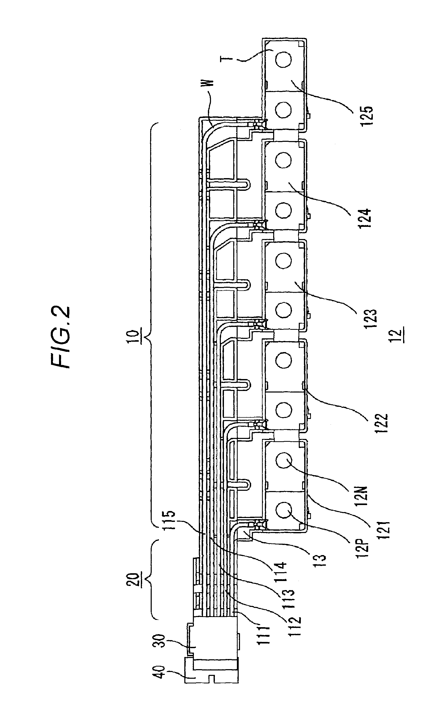
[0030]A wiring apparatus 10 according to a first embodiment shown in FIG. 1 is entirely formed by a plastic molding and is configured by a voltage detection wire housing portion 11, a terminal housing chamber 12 for housing battery terminals, and voltage detection wire extracting portions 13 for coupling the voltage detection wire housing portion 11 with the terminal housing chamber 12. Hereinafter, the explanation will be made as to the voltage detection wire housing portion 11, the terminal housing chamber 12 and the voltage detection wire extracting portions 13 in this order.

[0031]11 is Necessary>

[0032]In the case where the lithium ion battery is used for battery, according to the invention, instead of using an overcurrent prevention resistor element for each of the cells of the lithium ion batteries, a voltage detection wire is extracted for each of the cells of the lithium ion batteries and coupled to a connector, and the voltage detection wires are sequentially coupled t...

second embodiment

[0056]

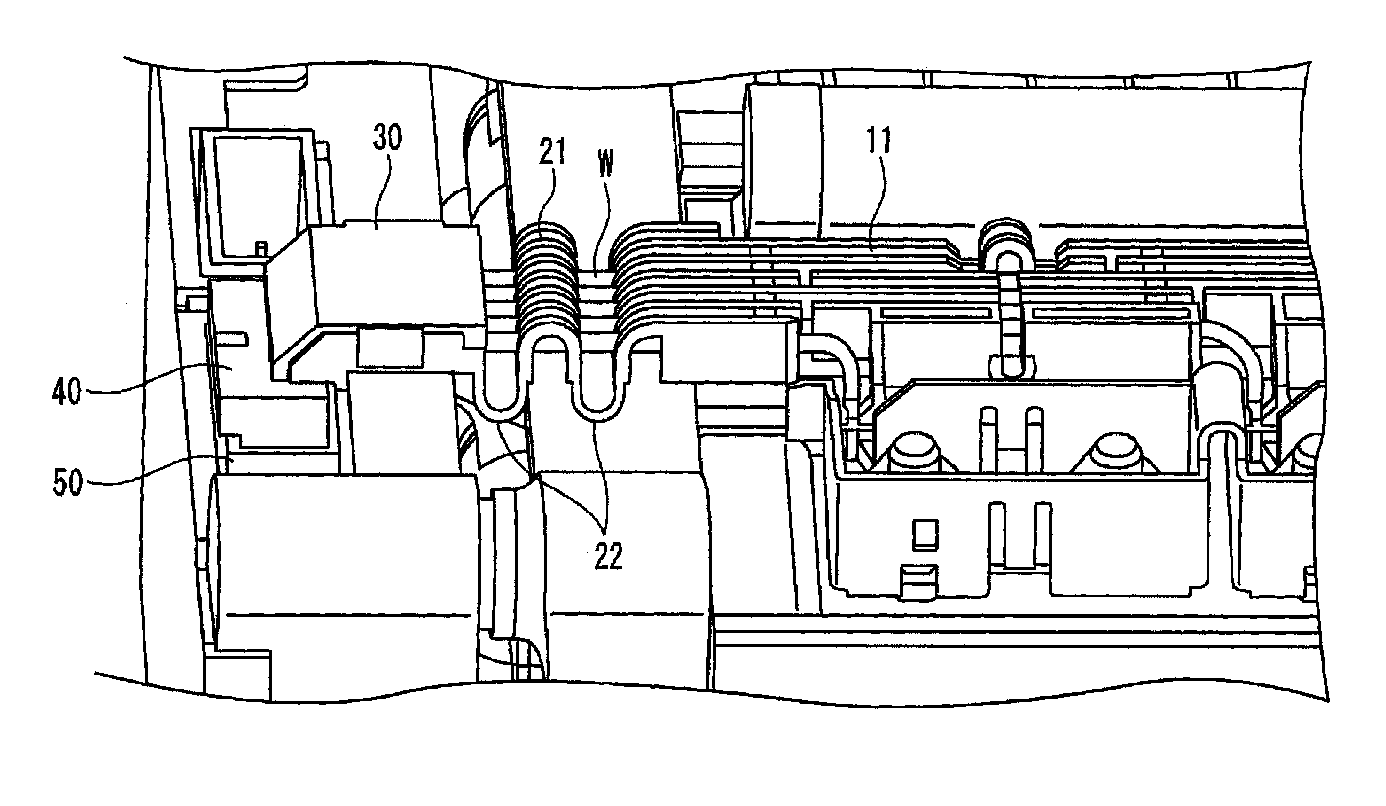
[0057]The feature of a second embodiment resides in that hinge portions are provided, each of which can partition the voltage detection wires W to each other so as not to directly contact mutually and compensate the design error by the shrink or expansion thereof while securing the insertion space of the connector on the coupling portion side of the connector 40.

[0058]FIGS. 4 to 6 are diagrams for explaining the wiring apparatus according to the second embodiment.

[0059]In FIGS. 4 and 5, there are shown the wiring apparatus 10 according to the first embodiment, a wiring apparatus 20 according to the second embodiment, a connector introducing portion 30 and the connector 40. The wiring apparatus 20 according to the second embodiment is configured in a manner that the entirety of a portion having grooves 21 continuing to the voltage detection wire housing portion 11 of the wiring apparatus 10 according to the first embodiment includes the hinge portions 22 each of which is bent i...


PUM

PropertyMeasurementUnit
conductiveaaaaaaaaaa
distanceaaaaaaaaaa
sizeaaaaaaaaaa

Abstract

A wiring apparatus includes a wire housing portion, terminal housing chambers and wire extracting portions. The wire housing portion is provided with a plurality of elongated housing grooves that respectively house wires therein and are disposed in parallel to each other, each of the grooves is divided at one or more portions by groove(s), and side walls and are coupled by a U-shaped elastic coupling member. Each terminal housing chamber houses a conductive metal plate for coupling the terminal of the battery and the terminal of the adjacent battery and couples adjacent terminal housing chambers and by a U-shaped elastic coupling member. Each of the wire extracting portions couples a wire housing groove and the terminal housing chamber to thereby extract the wire to the wire housing groove.

Description

TECHNICAL FIELD[0001]The present invention relates to a wiring apparatus used for an electric vehicle mounting lithium ion batteries thereon particularly and, in more detail, relates to a wiring apparatus which is arranged to avoid the direct contact between wires and to compensate the tolerance of a battery pitch and the design error of a distance to a PCB (printed circuit board) assembly attached to the side of a battery module from the battery module.BACKGROUND ARTWiring Apparatus Described in Patent Literature 1[0002]A wiring apparatus for compensating a positional deviation between a battery and an electronic part is known (see Patent Literature 1). The configuration described in Patent Literature 1 includes a plate body mounted on batteries that are aligned, terminals that are mounted on the plate body and couple the batteries with electric components, and a cover for mounting the terminals on the plate body, wherein each of the terminals is provided with a size difference com...

Claims


Application Information

Patent Timeline
Patent Type & Authority Patents(United States)
IPC IPC(8): H01R24/00H01M50/51H01M50/522H01M50/569
CPCH01M2/1083H01M2/206H01M10/482H01M10/0525Y02T10/7011Y02E60/10H01M50/522H01M50/51H01M50/569
Inventor HENMI, FUMITOSHI
Owner YAZAKI CORP
Why Eureka
Try Eureka