Electrical connector

a technology of electrical connectors and connectors, applied in the direction of coupling device connections, electrical discharge lamps, coupling device details, etc., can solve the problems of serious mechanism problems, signal loss, signal deformation and/or signal distortion, etc., to avoid direct impact of mating connectors, and enhance signal transmission quality and reliability

Inactive Publication Date: 2013-10-01
U D ELECTRONIC CORP
View PDF14 Cites 30 Cited by
  • Summary
  • Abstract
  • Description
  • Claims
  • Application Information

AI Technical Summary

Benefits of technology

[0008]The present invention has been accomplished under the circumstances in view. It is therefore the main object of the present invention to provide an electrical connector, which achieves optimal impedance matching and high structural stability, ensuring high signal transmission quality and reliability.
[0010]As the circuit board is accommodated in the tongue plate, when a mating connector is inserted into the metal shield, the direct impact by the mating connector is avoided.
[0011]Further, the surface area of the circuit lines of the circuit board may be configured subject to different impedance matching requirements, enhancing signal transmission quality and reliability.
[0012]Further, an electronic component, such as common-mode choke coil, filter resistor or filter capacitor may be installed in the circuit lines of the circuit board for removing noises, enhancing signal transmission quality and reliability.

Problems solved by technology

As a USB 3.0 connector uses a large number of conducting terminals that are arranged in a limited mounting area, approaching between two conducting terminals or curving of any conducting terminal may cause disturbance (static interference, electromagnetic interference, impedance matching, noise interface, crosstalk interference) during the transmission of a high-frequency signal.
Improper impedance matching can cause signal reflection and noise interference, resulting in signal loss, signal deformation and / or signal distortion.
When this problem occurs, the electronic system (computer or network system) may be unable to function normally.
When a USB 3.0 male connector is inserted into a USB 3.0 female connector, the arrangement of the springy metal contact terminals at the circuit board design of tongue plate of the USB 3.0 female connector may causes serious mechanism problems.
The first problem is that the positioning of the front contact portions of the springy metal contact terminals on the top side of the circuit board design of tongue plate may be directly impacted by the mating metal contact terminals of the USB 3.0 male connector, due to positioning displacement or large tolerance, causing disconnection of the spring metal contact terminals from the circuit board design of tongue plate.
The second problem is that the springy metal contact terminals may be squeezed toward the circuit board design of tongue plate by a lateral force upon insertion of the USB 3.0 male connector into the USB 3.0 female connector, causing damage or disconnection of the rear soldering portions of the springy metal contact terminals from the circuit board design of tongue plate.
A third problem is that the circuit board design of tongue plate has no room for allowing the springy metal contact terminals to be elastically and heavily deformed and the springy metal contact terminals may be permanently deformed.

Method used


Image

  • Electrical connector
  • Electrical connector
  • Electrical connector

Examples


Embodiment Construction

[0021]Reference will be made in detail to the preferred embodiment of the invention, an example of which is illustrated in the accompanying drawings. Wherever possible, like reference numbers are used in the drawings and the description to refer to like parts.

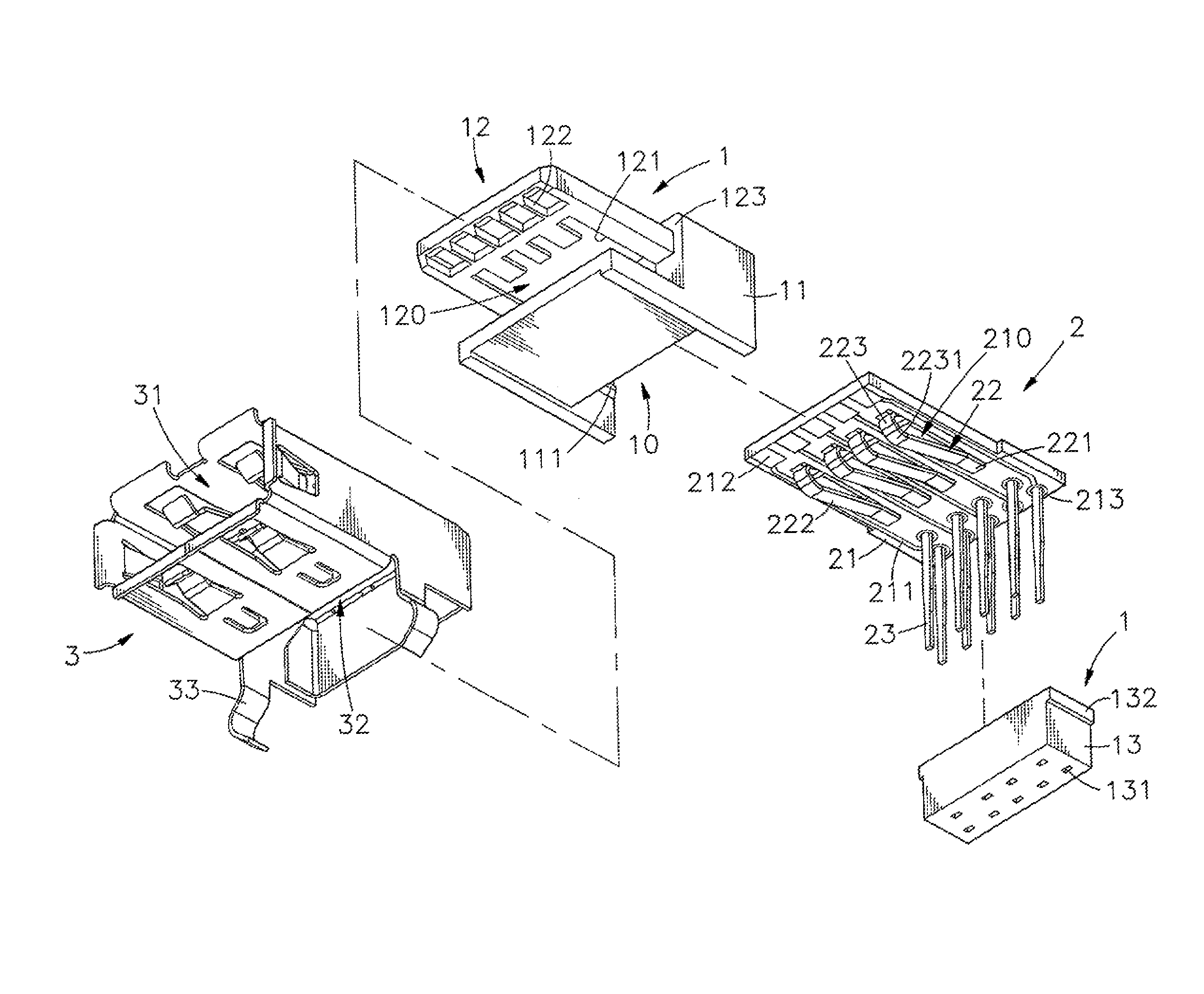
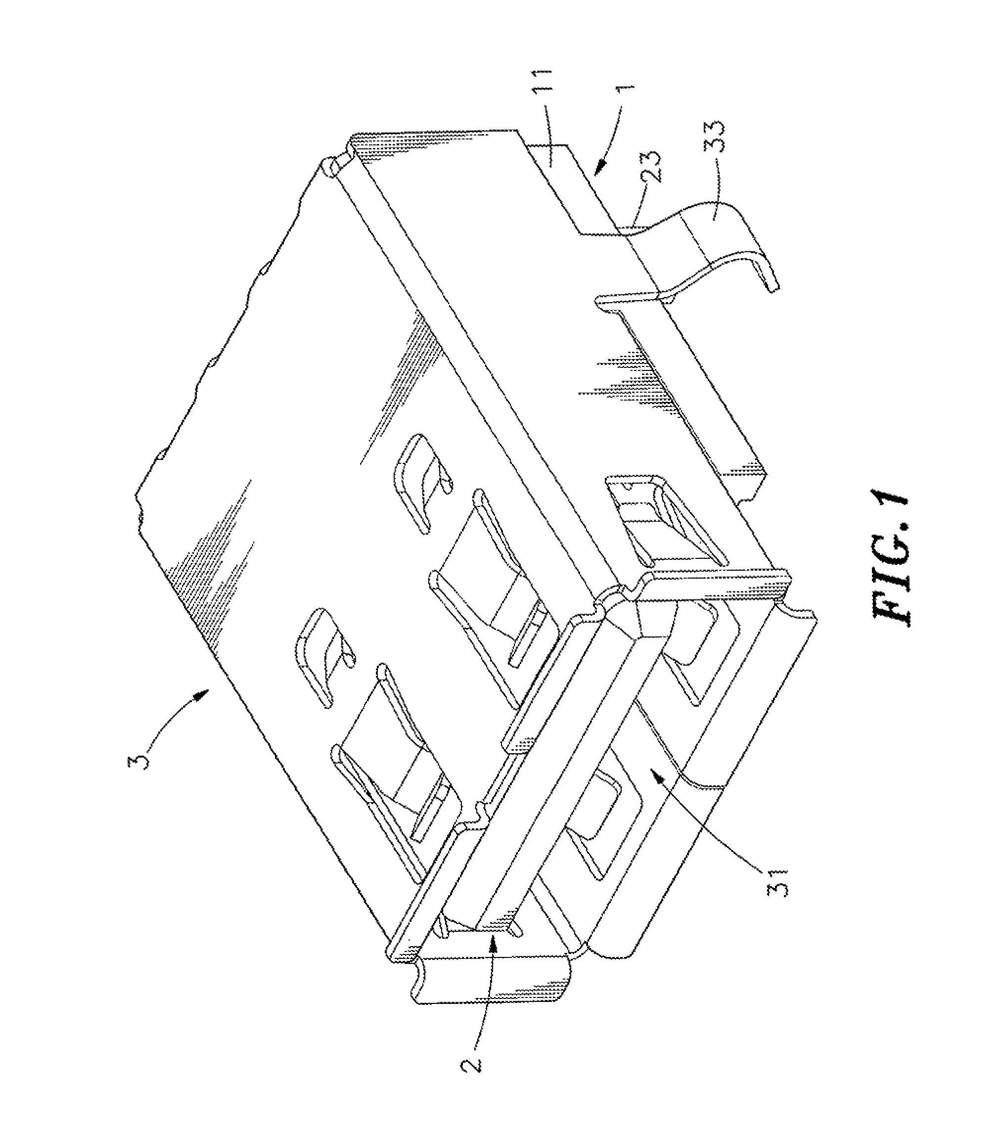
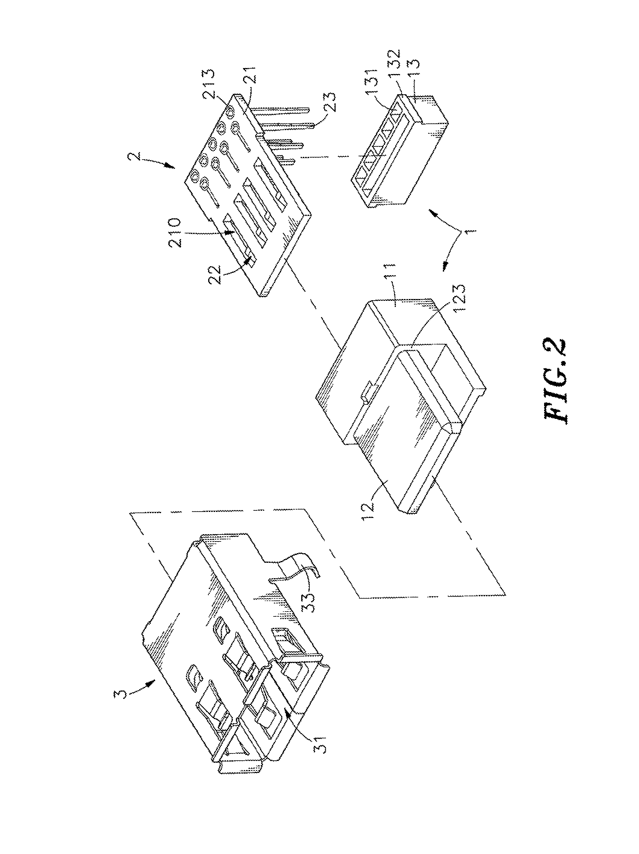
[0022]Referring to FIGS. 1, 2, 3 and 4, an elevational view, an exploded view, an exploded view viewed from another angle and a sectional side view in an enlarged scale of an electrical connector in accordance with the present invention are respectively shown. The electrical connector comprises an electrically insulative holder member 1, a signal module 2, and a metal shield 3.

[0023]The electrically insulative holder member 1 comprises a holder base 11, a tongue plate 12, and a partition block 13. The holder base 11 defines an accommodation open chamber 10 in the rear bottom side thereof, and two inside retaining flanges 111 symmetrically disposed at two opposite lateral sides in the accommodation open chamber 10. The tongue pl...


PUM


Abstract

An electrical connector includes an electrically insulative holder member, a signal module formed of a circuit board with longitudinal terminal holes, circuit lines, electrical contacts and via-holes, metal contact terminals and metal mounting terminals, and a metal shield. The metal contact terminals have rear soldering end portions thereof respectively soldered to respective circuit lines, front contact portions thereof positioned in front ends of the longitudinal terminal holes of the circuit board and middle suspension arms thereof connected between the rear soldering end portions and the front contact portions and suspending below the longitudinal terminal holes. The electrical contacts of the circuit board are positioned in respective bottom contact holes of the tongue plate. The circuit lines electrically connect the electrical contacts and the metal contact terminals to the via-holes. The surface area of each circuit line may be modified to adjust impedance, reducing interference.

Description

BACKGROUND OF THE INVENTION[0001]1. Field of the Invention[0002]The present invention relates to electrical connector technology and more particularly, to such an electrical connector, which achieves optimal impedance matching and high structural stability, ensuring high signal transmission quality and reliability.[0003]2. Description of the Related Art[0004]Following fast development of computer technology, high mobility notebook computer has been well developed and widely used by people to substitute for desk computer. Further, when connecting a computer to a peripheral apparatus for transmitting data or signal, a peripheral interface means is necessary. USB (universal serial bus) is the mainstream interface, having hot plug function.[0005]Further, following the market trend to make computers and peripheral devices having a small size characteristic, the problem of internal signal interference due to magnetic effects must be taken into account. Interferences may come from conducte...

Claims


Application Information

Patent Timeline
Patent Type & Authority Patents(United States)
IPC IPC(8): H01R12/00
CPCH01R13/6658H01R24/62
Inventor CHEN, PO-JUNG
Owner U D ELECTRONIC CORP
Why Eureka
Try Eureka