Suction tip for surgical instruments

a surgical instrument and suction tip technology, applied in the field of surgical instruments with suctioning tips, can solve problems such as the limitation of suctioning in narrow range areas

Active Publication Date: 2013-10-01
HAJARIAN HAMID CYRUS +1
View PDF1 Cites 12 Cited by
  • Summary
  • Abstract
  • Description
  • Claims
  • Application Information

AI Technical Summary

Benefits of technology

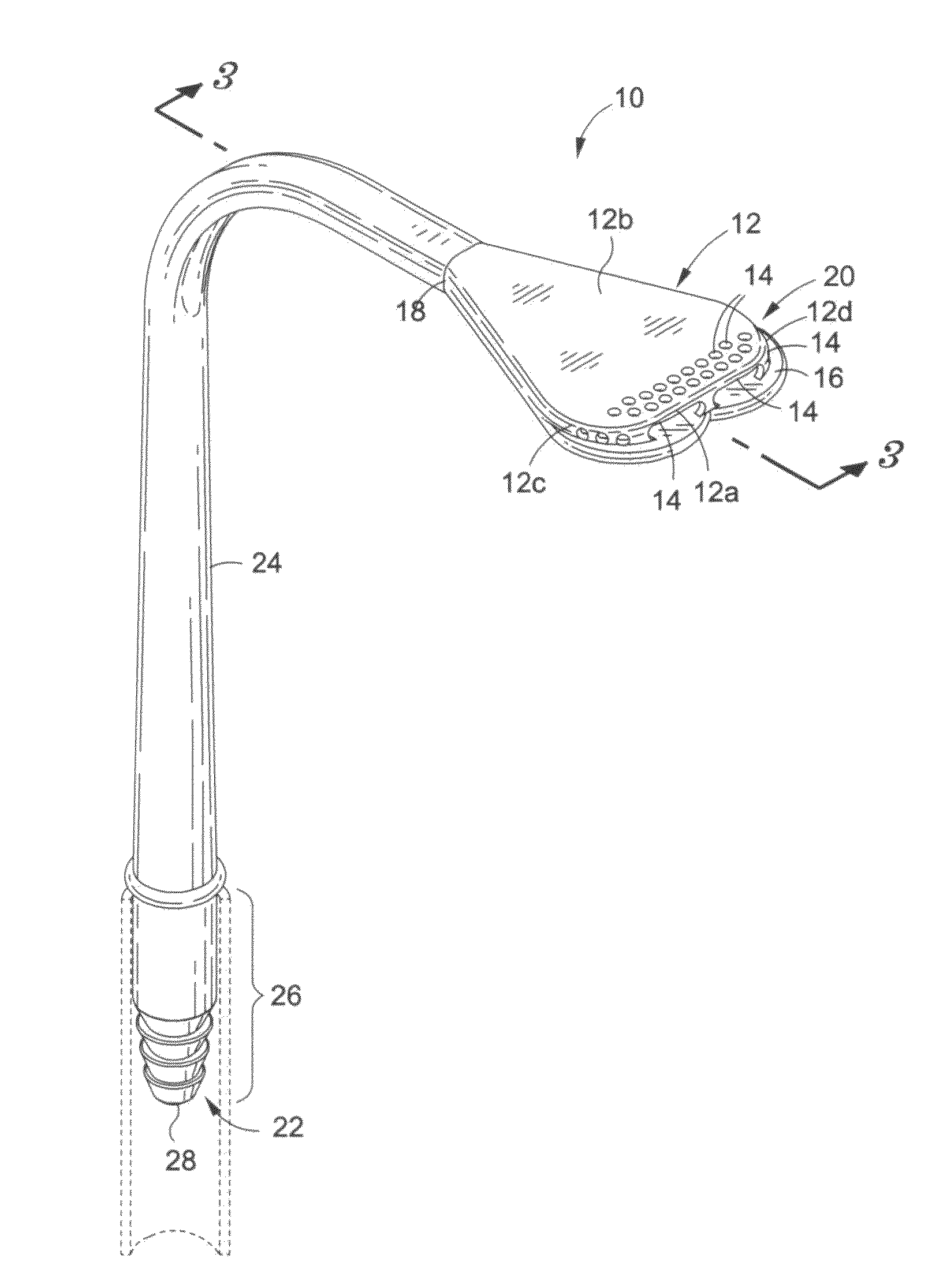
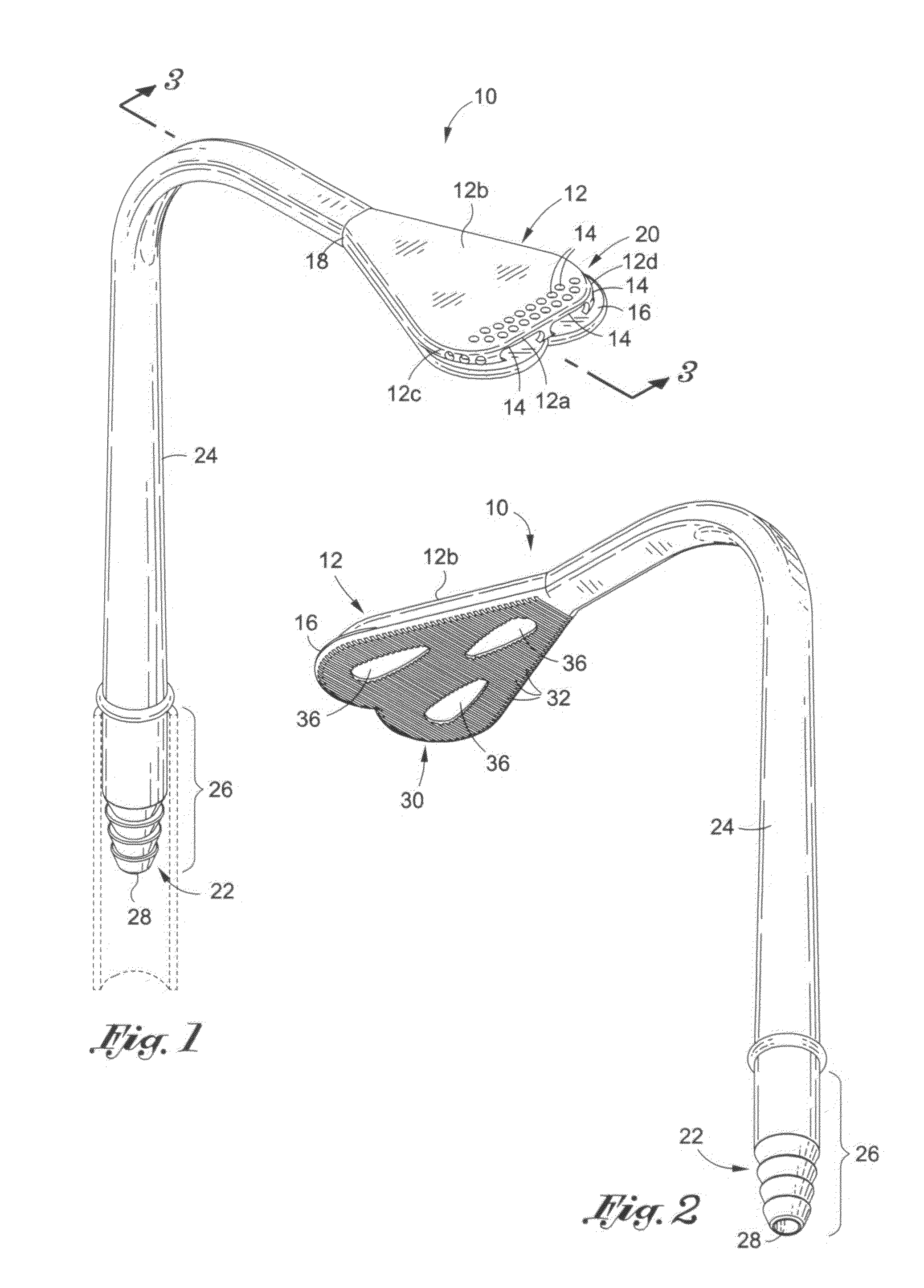
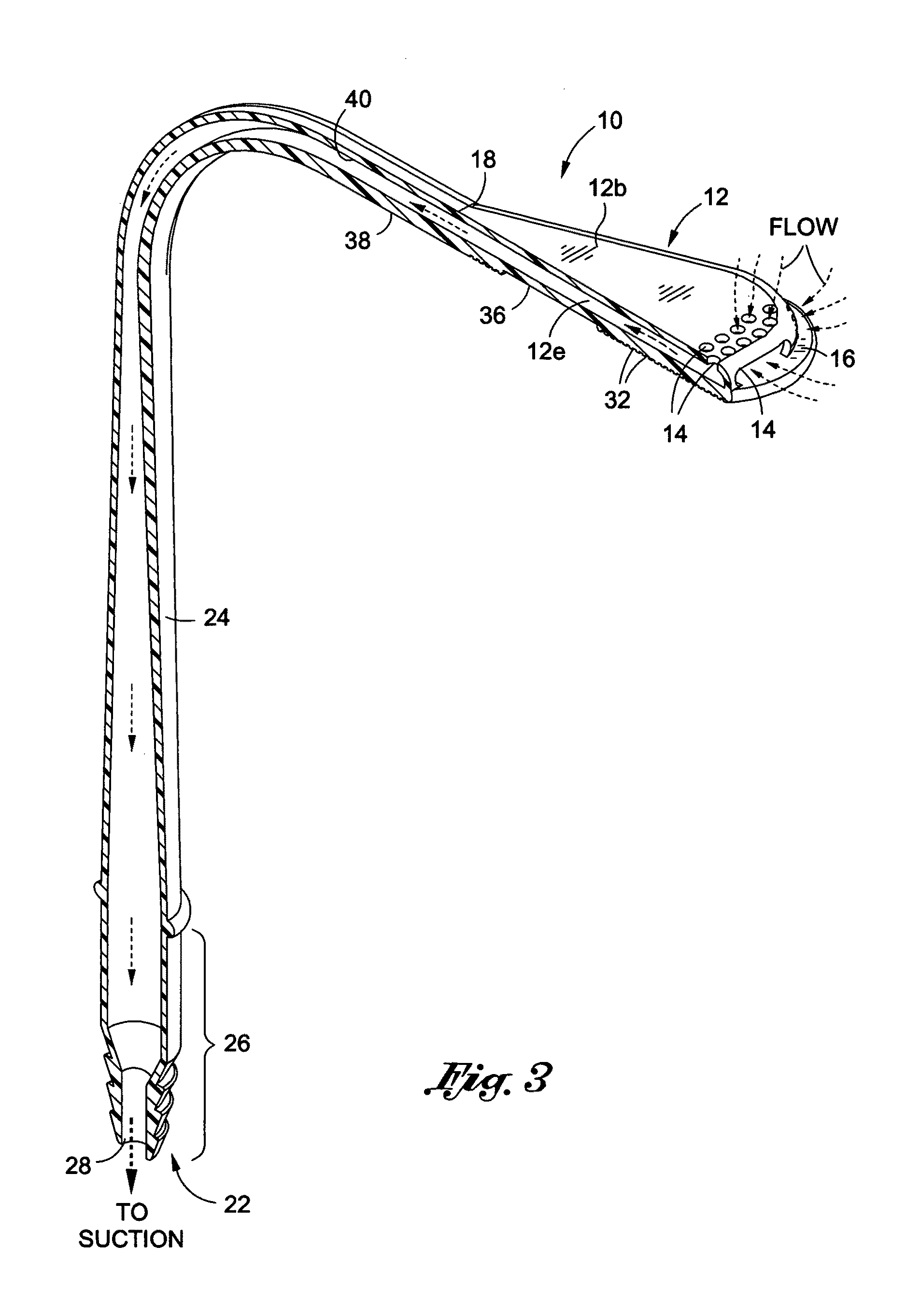
[0005]It is an object of the present invention to provide an improved suctioning tip for a surgical instrument to cover a wider range of evacuation without creating any trauma to surrounding tissues. The suction tip apparatus comprises a hollow housing which has a proximal end and a distal end. At its distal end, the widened tip portion has a plurality of suction ports located at its front, on top, on its right side and also on left side. These suction ports along with the widened tip portion allow for suctioning of a wider range of an area. Furthermore a ledge portion provides a clear space between the suction ports and the tissue for means of evacuation and collection of fluid. An exit port near the proximal end is also provided for discharging fluid.

Problems solved by technology

Although the prior art devices eliminate some issues associated with this type of problem, there are limitations regarding suctioning of narrow range areas.

Method used


Image

  • Suction tip for surgical instruments
  • Suction tip for surgical instruments
  • Suction tip for surgical instruments

Examples


second embodiment

[0028]FIGS. 7-9 illustrate the improved suction tip 100 that can be adaptable and provide a wider range suctioning tip to an existing surgical tube 200. The tube's tip 220 snugly fits at the proximal end 122 of the suction tip 100. Once the tip 220 is secured into the distal end lumen 140, the tube's body 224 can be placed into the “U” shaped suction tip. The purpose of the “U” shape is to eliminate any tube 200 rotation and securely keep the suction tube in place with respect to the suction tip 100.

third embodiment

[0029]the present invention is shown in FIGS. 10-11. In this embodiment, the suction tip 300 is shown as a separated piece that is mountable to an existing surgical retractor 400 by placing it over the retractor tip 420. The suctioning tip apparatus 300 can be secured by means of attaching to the surgical retractor such as a clip 330, which is located at the bottom portion of the distal end 322 of the suctioning tip 300. Other means of attachment include adhesive or any fasteners between these two parts. Once the suction tip apparatus is placed over the surgical retractor, it can be connected to a vacuum tube 360 which provides a suction source to the tip portion.

[0030]A modified version of the suction tip apparatus 500 is shown in FIG. 12. In this embodiment, a mirror 520 has been added to the top surface 512b of the suction tip portion. In addition, at its proximal end, a connection port has been added which includes various sizes of connection to adapt different sizes of vacuum h...


PUM


Abstract

A suction tip for a surgical instrument includes a hollow housing having a top flat wall and a bottom flat wall and including a proximal end and a distal end. The distal end has a widened tip portion that is wider than the proximal end. The distal end may have a plurality of suction ports located at its front, top, right side and left side of the widened tip portion. Furthermore a ledge portion may protrude outwardly past a terminal end of the top flat wall to provide a clear space between the suction ports and tissue for evacuation of fluid in the clear space.

Description

[0001]This application claims priority to Provisional application Ser. No. 61 / 280,873 filed on Nov. 10, 2009, the entire contents of which is incorporated by reference herein.FIELD OF THE INVENTION[0002]The present invention relates to a surgical instrument with suctioning tip. More particularly the suctioning tip encompasses a wide range of evacuation.BACKGROUND OF THE INVENTION[0003]The importance of surgical retractors is well known in surgical procedures. A surgeon needs an exposure as best as possible while inflicting a minimum of trauma to the surrounding tissue. In some operations, such as oral surgery, a surgeon uses the tongue retractor to protect a patient's tongue from the medical procedure. An assistant surgeon or nurse performs continuous suctioning of fluid by placing a suction tube into the patient's mouth and performing the necessary evacuation to protect the patient from inhaling or swallowing fluids and scattered debris. Every time the assistant performs the evacua...

Claims


Application Information

Patent Timeline
Patent Type & Authority Patents(United States)
IPC IPC(8): A61B1/32A61C17/06A61C17/14
CPCA61M1/008A61M1/84
Inventor HAJARIAN, HAMID CYRUSHAMIDI, VAHID
Owner HAJARIAN HAMID CYRUS
Why Eureka
Try Eureka