Hydroponic growing system

a growing system and hydroponic technology, applied in botany apparatus and processes, agriculture, agricultural gas emission reduction, etc., can solve the problems of increasing the evaporation of liquid nutrient solution, essentially drowning of plants, and insufficiently facilitating the growth of air roots in the prior art, and achieve the effect of facilitating the level floatation of the planting tray

Active Publication Date: 2013-10-08
MB3 L L C
View PDF21 Cites 37 Cited by
  • Summary
  • Abstract
  • Description
  • Claims
  • Application Information

AI Technical Summary

Benefits of technology

[0018]In a further embodiment, the hydroponic growing system includes a plurality of chamber walls disposed in the air channel dividing the air channel into a series of chambers to resist the shifting of air through the air channel and facilitate level floatation of the planting tray.

Problems solved by technology

This creates issues, particularly with larger plants, as the prior art planting trays provides no flexibility in managing the spacing of the plants.
Further, the hydroponic growing systems in the prior art fail to adequately facilitate the growth of “air roots”.
Also, with this type of system, once the air roots emerge, if the liquid level rises and the air roots are submerged, the plant will essentially drown.
With fully floating systems in which the planting tray always is positioned at the water level, there is never an opportunity for air root growth which significantly enhances plant growth.
Additionally, these type of hydroponic growing systems are often placed outside and the prior art does not disclose any system that prevents the sunlight from entering the nutrient reservoir.
This can lead to increased evaporation of the liquid nutrient solution and the unwanted growth of algae in the reservoir.

Method used


Image

  • Hydroponic growing system
  • Hydroponic growing system
  • Hydroponic growing system

Examples


Embodiment Construction

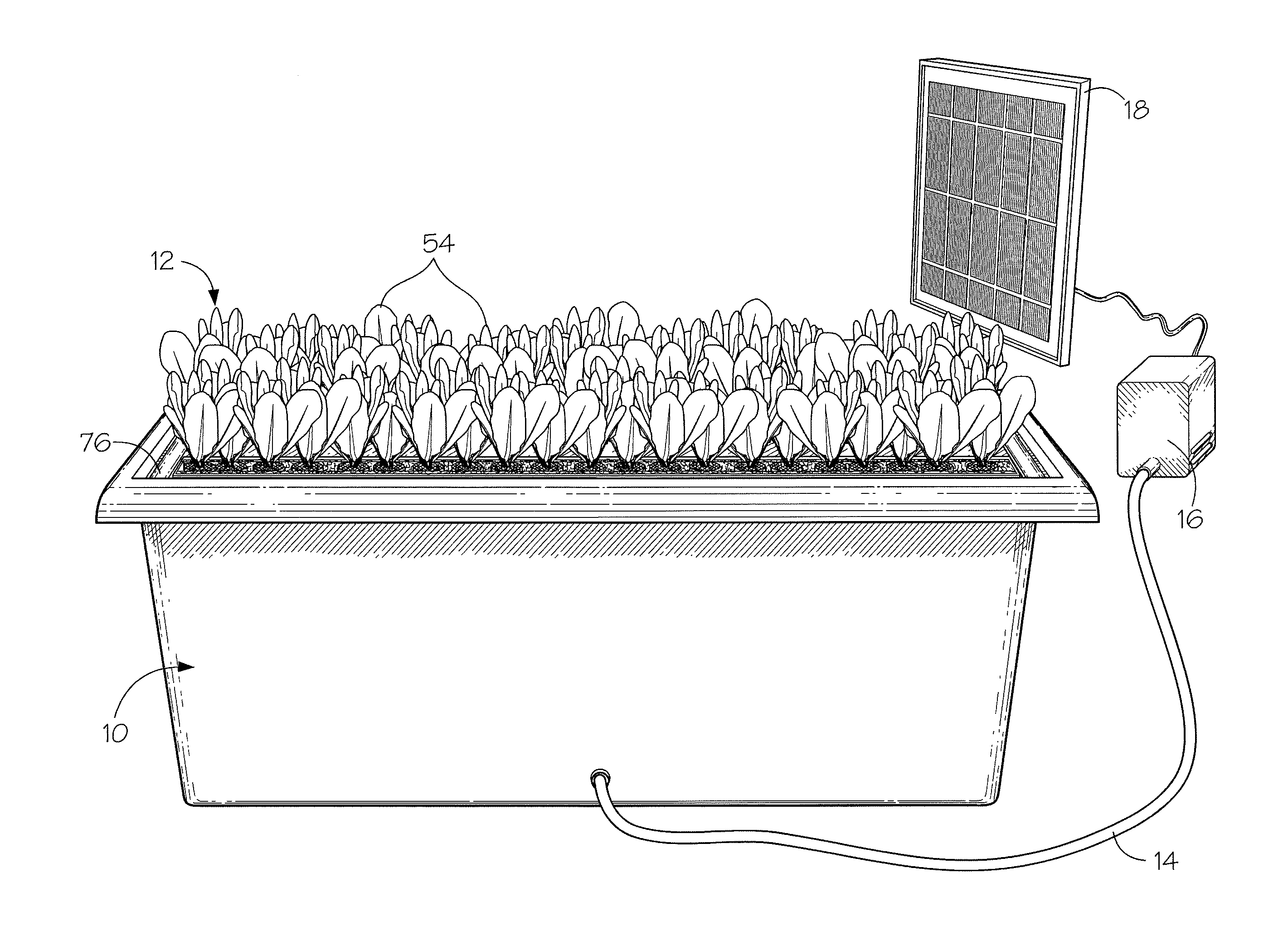
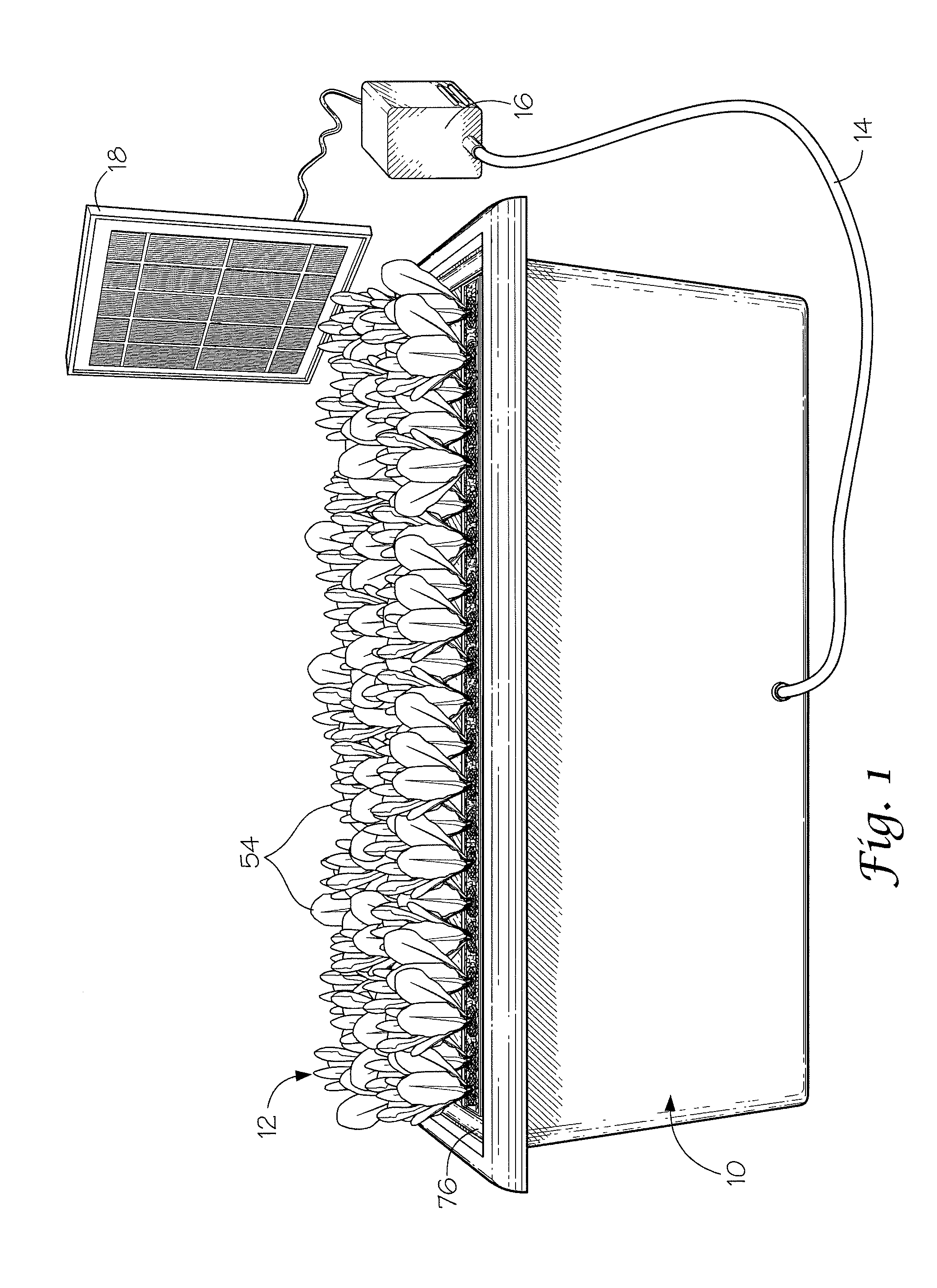
[0033]With reference to the drawings, the invention will now be described in more detail. Referring to FIG. 1, a hydroponic growing system is shown in a functioning arrangement according to the present invention. In the illustrated embodiment, the system includes a nutrient reservoir, designated generally as 10. The nutrient reservoir 10 holds a liquid plant nutrient solution, which is typically water mixed with various growth supplements. A planting tray, designated generally as 12, is disposed in reservoir 10 that is adapted for floating at the surface of the liquid plant nutrient solution in the reservoir 10. To help oxygenate the liquid in reservoir 10 to facilitate plant growth, an air line 14 passing through a sidewall of reservoir 10. Air line 14 is connected to an air pump 16 for introducing air into the liquid plant nutrient solution of reservoir 10. Preferably, air pump 16 is powered by a solar panel 18 as shown in the illustrated arrangement, to provide for a self-contain...


PUM


Abstract

A hydroponic growing system including a nutrient reservoir and a planting tray having a perimeter air channel for floating on a liquid in the reservoir. A continuous planting trough is included in the planting tray for growing multiple plants in an un-segmented arrangement which is defined by a series of laterally spaced support arms extending across and underneath an opening in a support plate for carrying plant growth materials. The planting tray floats in the reservoir so that a majority of the planting trough is disposed above the liquid in the reservoir to allow for lateral air root growth. A flexible flange is carrier around the perimeter of the planting tray engaging the reservoir to form a light barrier between the planting tray and the reservoir. An air line passes into the reservoir which is connected to an air pump for introducing air into the liquid in the reservoir.

Description

BACKGROUND OF THE INVENTION[0001]1) Field of the Invention[0002]The present invention relates to hydroponic growing systems, and more particularly, to an improved floating planting tray having a continuous planting trough, light control elements and providing for continuous air root growth during the growing cycle.[0003]2) Description of Related Art[0004]Various hydroponic growing systems are known in the prior art. The type of self-contained growing units for non-commercial home use that have a floating planting tray also have fixed positions for planting individual plants. This creates issues, particularly with larger plants, as the prior art planting trays provides no flexibility in managing the spacing of the plants. Accordingly, there is a need to allow for adjustable spacing between plants in these type of hydroponic growth systems.[0005]Further, the hydroponic growing systems in the prior art fail to adequately facilitate the growth of “air roots”. Air roots grow laterally ou...

Claims


Application Information

Patent Timeline
Patent Type & Authority Patents(United States)
IPC IPC(8): A01G31/00
CPCA01G31/02Y02P60/21
Inventor BRYAN, III, MORRIS
Owner MB3 L L C
Why Eureka
Try Eureka