Stent

a technology of annular stents and radial expansion, which is applied in the field of radially expanding annular stents, can solve the problems of not meeting other government regulatory or quality control requirements, requiring strain, and changing shape necessitating strain

Active Publication Date: 2013-10-08
CR BARD INC
View PDF200 Cites 25 Cited by
  • Summary
  • Abstract
  • Description
  • Claims
  • Application Information

AI Technical Summary

Benefits of technology

[0009]According to the present invention, a stent as identified above is improved by arranging that, for the connector struts, the thickness of the struts is smaller than the ambient wall thickness of the stent.
[0014]As will be seen below, an attractive feature of the present invention is that it enables the creation of stent matrices that combine good radial force against bodily tissue with good flexibility both in the radially expanded and in the radially compressed dispositions in a design in which the connectors are simple, short, substantially straight struts.
[0015]The stiffness of a strut of a stent matrix is proportional to the strut width but, in relation to the strut thickness, it goes up with the cube of the thickness. A small reduction of strut thickness can therefore yield large gains in flexibility. This property is utilised in the present invention by providing connector struts with a smaller radial wall thickness than that of the stent annulus.

Problems solved by technology

Such a change of shape necessitates the occurrence of strain within the matrix.
However, building a stent annulus with convoluted or serpentine connectors adds to the complexity of manufacture and might not assist in meeting other government regulatory or quality control requirements.

Method used


Image

  • Stent
  • Stent
  • Stent

Examples


Embodiment Construction

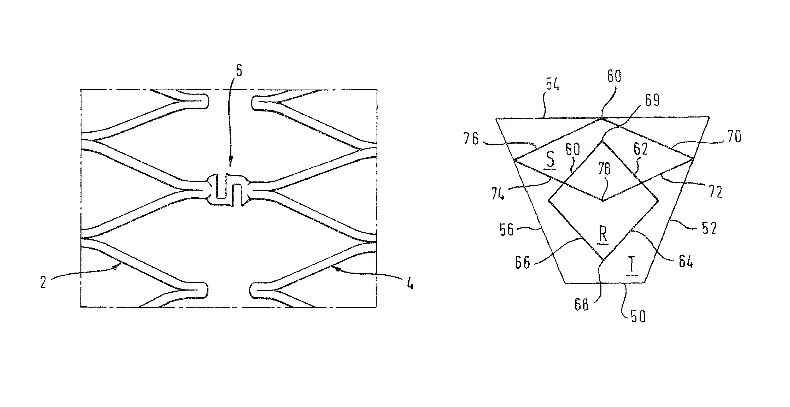
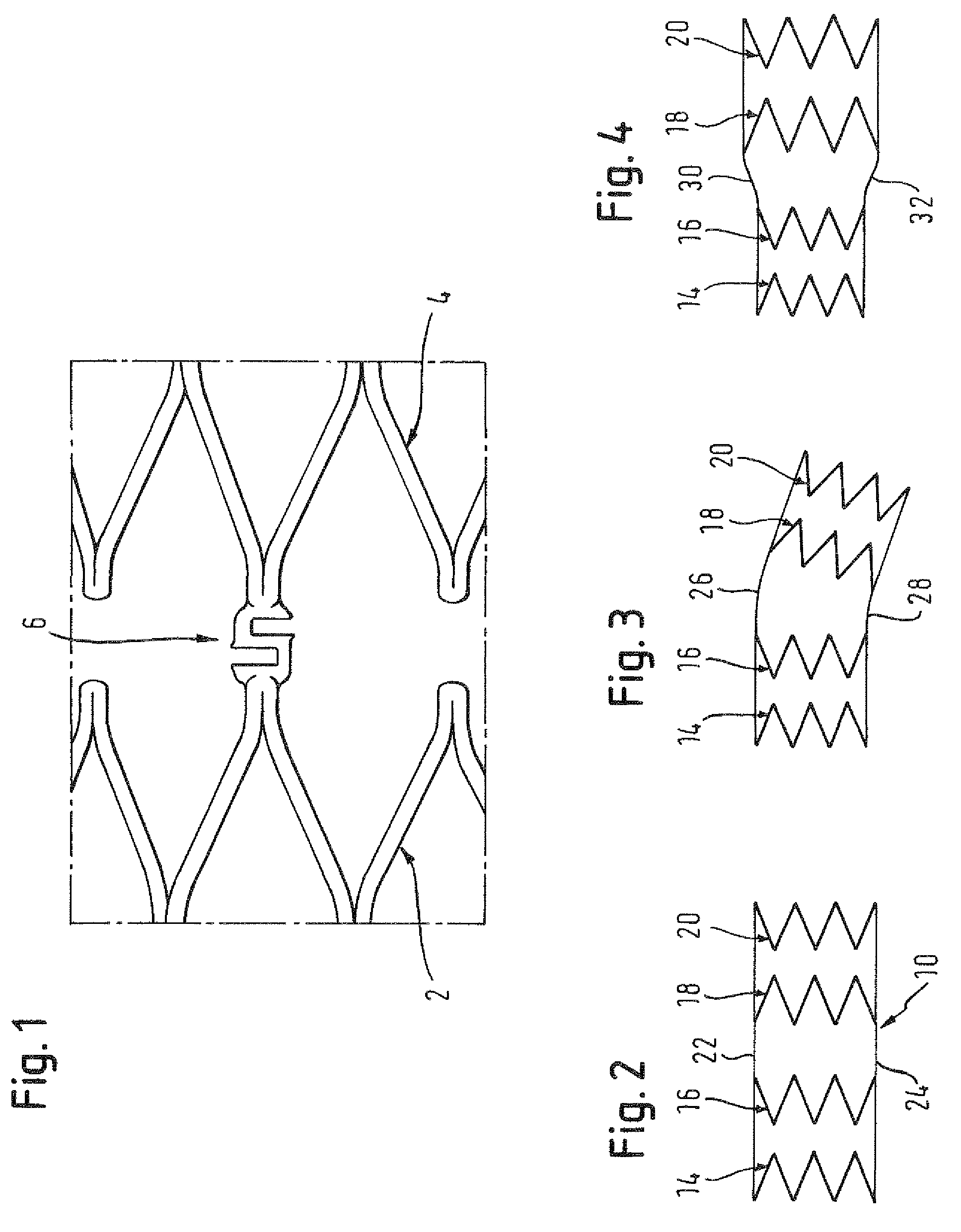
[0021]Looking first at FIG. 1, the skilled reader will recognise portions of two adjacent zig-zag stenting rings 2, 4 and a single connector 6 of those two adjacent rings, central in the drawing Figure. That connector 6 shows a serpentine form, resembling the letter “S” lying on its side and with the base of the letter S contiguous with one of the two zig-zag stenting rings 2, 4 and the top of the letter S contiguous with the other of the two stenting rings. Self-evidently, the serpentine form of the connector 6 provides the stent matrix with capacity to undergo strain, somewhat additional to the capacity it would have if the serpentine connector 6 were to be replaced by a short straight link connecting the two zig-zag stenting rings 2, 4.

[0022]Turning to FIG. 2, we see diagrammatically a stent 10 composed of four zig-zag stenting rings 14, 16, 18 and 20 like the zig-zag rings shown in FIG. 1. The longitudinal straight lines 22 and 24 indicate the general form of the annulus of the ...


PUM

PropertyMeasurementUnit
distanceaaaaaaaaaa
shape memoryaaaaaaaaaa
wall thicknessaaaaaaaaaa

Abstract

A radially expansible annular stent is disclosed. The stent comprises a plurality of stenting turns around a lumen centred on a longitudinal axis. Adjacent turns of the stent are joined by connector struts. The stent annulus has a wall thickness related to the material from which it is formed. The radial thickness of the connector struts is smaller than that of the stent annulus. A method of making such a stent is also disclosed. The method includes cutting the connector struts from a tubular workpiece with a laser beam. The laser beam is aimed so as to be offset from a longitudinal axis of the workpiece to provide the reduced radial thickness of the connector struts.

Description

PRIORITY[0001]This application is a U.S. national stage application under 35 USC §371 of International Application No. PCT / EP2007 / 062155, filed Nov. 9, 2007, claiming priority to United Kingdom Patent Application No. 0622465.3, filed Nov. 10, 2006, each of which is incorporated by reference in its entirety into this application.FIELD OF THE INVENTION[0002]This invention relates to a radially-expansible annular stent comprising a plurality of stenting turns around a lumen centered on a longitudinal axis, with adjacent turns being joined by connector struts, the stent annulus having a maximum wall thickness that is related to the material of which it is formed.BACKGROUND ART[0003]In the field of radially expansible annular stents that are called upon, in use, to resist a radially inwardly directed force from surrounding bodily tissue, in order to maintain a bodily lumen patent, there is a contradictory design requirement. On the one hand, the stent must be strong enough to keep the lu...

Claims


Application Information

Patent Timeline
Patent Type & Authority Patents(United States)
IPC IPC(8): A61F2/86A61F2/915
CPCA61F2/915A61F2002/91541A61F2230/0054A61F2250/0036A61F2002/91558A61F2230/0069A61F2240/002B23K2103/42A61F2240/001A61F2250/0039A61F2/86B23K26/38A61F2/89B23K26/402
Inventor WACK, THILOHAAS, THOMAS
Owner CR BARD INC
Why Eureka
Try Eureka