Two-piece track system

a track system and two-piece technology, applied in the direction of girders, shock-proofing, walls, etc., can solve the problems of limited orthogonal movement of studs, difficult to identify the proper location for attachment of exterior sheathing elements, etc., to facilitate the creation of seals and enhance or maximize deflection length

Active Publication Date: 2013-10-15
CEMCO LLC
View PDF186 Cites 78 Cited by
  • Summary
  • Abstract
  • Description
  • Claims
  • Application Information

AI Technical Summary

Benefits of technology

[0012]Some embodiments are directed toward an improved slotted track device and system capable of use in building construction. It is well-suited for use in the exterior wall of a building, but can be used in other applications as well. The device includes a plurality of slots located along at least one flange of the slotted track. The slots permit attachment of the slotted track to a wall stud or studs. The slots also allow for generally orthogonal movement of the wall studs relative to the slotted track during an earthquake or some other event where movement of the studs is desired.
[0013]Furthermore, it can be desirable for the intumescent material to be secured to a track member that is separate from the top or bottom track that directly receives or supports the studs, or separate from the stud in the case of a side wall gap. Such an arrangement enhances or maximizes the deflection length available for a slotted track (or other dynamic header) for a given flange length by separating the intumescent-carrying flanges from the slotted flanges. The arrangement also provides flexibility in that it allows different header tracks, footer tracks or studs to be used in combination with a single track incorporating the intumescent material. In addition, a two-piece track or track / stud arrangement can facilitate the creation of a seal between the components of the wall assembly and the adjacent structure. The intumescent material can be placed at a suitable location on the track member, such as along a side flange and / or a side edge portion of the web. Preferably, the header track, bottom track or stud is snugly received in the track member incorporating the intumescent, such that little or no gap is present between them.

Problems solved by technology

It has been discovered by the present inventor that it is also often difficult to identify the proper location for attachment of an exterior sheathing element along the flange of a slotted track.
If the sheathing elements are misaligned and overlap a portion of the plurality of slots, the generally orthogonal movement of the studs can be limited due to interference between the stud fastener, which passes through one of the plurality of slots, and the sheathing element.

Method used


Image

  • Two-piece track system
  • Two-piece track system
  • Two-piece track system

Examples


Embodiment Construction

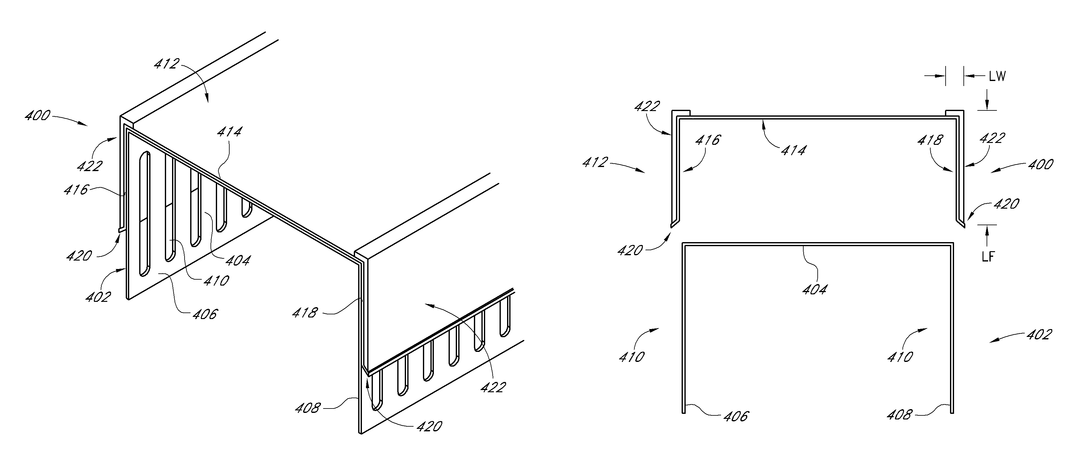
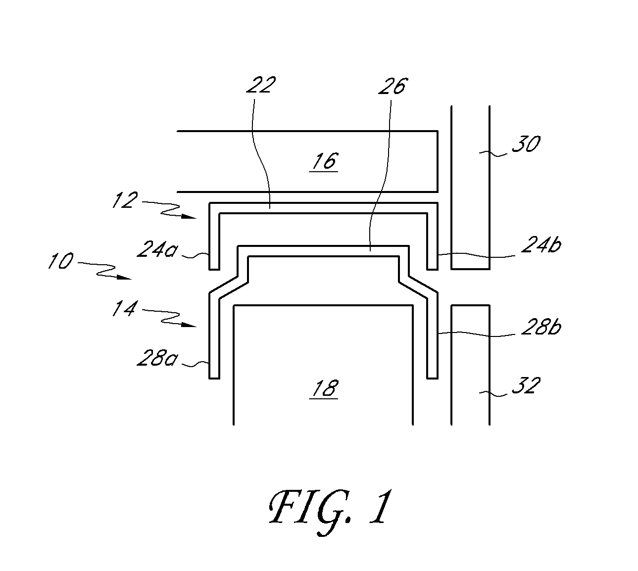
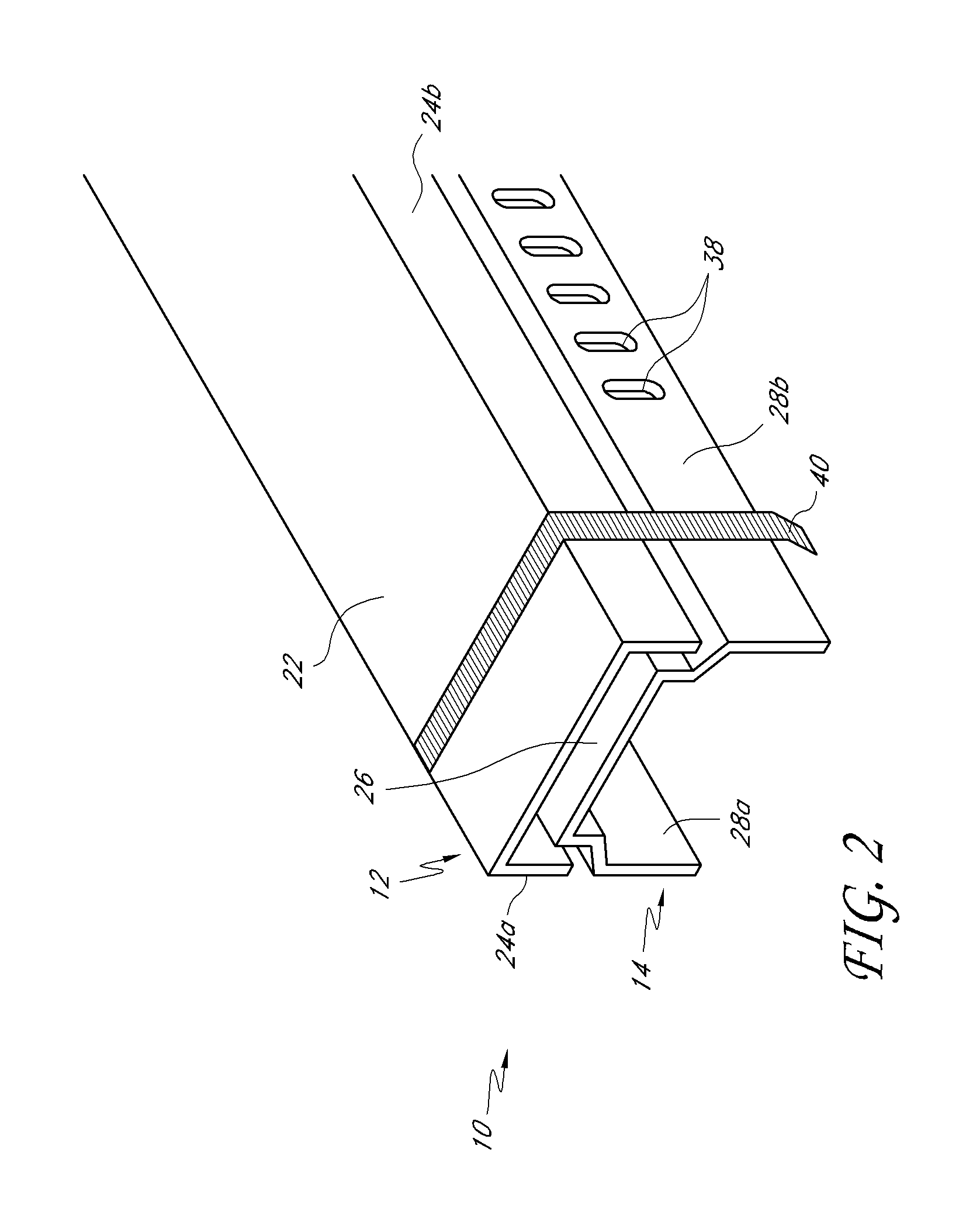
[0045]Referring to FIG. 1, a first embodiment of the inventive track assembly 10 comprises a first outer track 12 and a second nested track 14 therewithin. The track assembly is configured to be attached via one of various known fastening means to a ceiling surface 16 of a building and to engage a plurality of vertical stud members 18. The outer track 12 comprises a web 22 and two side flanges 24a and 24b. Similarly, the inner track 14 comprises a web 26 and two side flanges 28a and 28b. The outer and inner tracks 12, 14 are matingly configured so that the inner track 14 can nest within the outer track 12 when assembled to prevent generally side-to-side movement but permit relative longitudinal movement along the length of the tracks.

[0046]It is desirable that the greatest width of the outer track 12 be no greater than the greatest width of the inner track 14; i.e., equal to or less than the greatest width of the inner track 14. In the embodiments shown by example in FIGS. 1 and 2, ...


PUM


Abstract

A fire-rated receiver channel includes at least one intumescent or other fire-resistant material strip. The receiver channel can nest with a framing member, such as metal tracks, headers, header tracks, sill plates, bottom tracks, metal studs, wood studs or wall partitions, and placed at a perimeter of a wall assembly to create a fire block arrangement. In other arrangements, a track assembly includes two nested tracks, an inner track and outer track. The assembly is designed so that the outside width of the outer track is equal to or less than the outside width of the inner track to present a substantially flush external surface for attachment of exterior sheathing elements when the assembly is used in an external wall.

Description

RELATED APPLICATIONS[0001]Related applications are listed in an Application Data Sheet (ADS) filed with the present application. The entirety of each application listed in the ADS is hereby incorporated by reference herein. Also incorporated by reference herein in their entireties are U.S. Pat. No. 7,617,643 entitled Fire-Rated Wall Construction Product, U.S. Publication No. 2009 / 0178369 entitled Exterior Wall Construction Product, U.S. Publication No. 2011 / 0113709 entitled Wall Gap Fire Block Device, System and Method, and U.S. patent application Ser. No. 13 / 083,328, filed Apr. 8, 2011, entitled Fire-Rated Wall Construction Product.BACKGROUND OF THE INVENTION[0002]1. Field of the Invention[0003]This application is directed toward a two-piece track system for use in building construction, particularly for use in the interior and / or exterior wall of a building.[0004]2. Description of the Related Art[0005]Two-piece track systems for use in building construction are generally well know...

Claims


Application Information

Patent Timeline
Patent Type & Authority Patents(United States)
IPC IPC(8): E06B1/04E04C2/00E04C3/00E04H1/00
CPCE04B2/828E04B1/941E04B1/38E04B2/7411E04B1/944E04B2/768E04C3/09E04B2/7457E04C2003/0417E04C2003/0473E04B2/88E04B1/946E04B1/947E04B2/58E04B1/948E04B2/7403
Inventor PILZ, DONALD A.POLIQUIN, RAYMOND E.SESMA, FERNANDO HERNANDEZ
Owner CEMCO LLC
Why Eureka
Try Eureka