Occipito-cervical fixation assembly and method for constructing same

a technology for occipitocervical and occipital nerves, which is applied in the field of orthopedic implantable device technology, can solve the problems of inability to provide desirable configurability options, difficulty in adjusting existing systems, and time-consuming adjustment, and achieve the effect of facilitating plate contouring

Active Publication Date: 2013-10-15
ORTHOFIX US LLC
View PDF63 Cites 19 Cited by
  • Summary
  • Abstract
  • Description
  • Claims
  • Application Information

AI Technical Summary

Benefits of technology

[0006]Embodiments of the occipital plate may comprise grooves for facilitating contouring of the plate. The plate may also comprise one or more apertures for receiving bone fasteners that may secure the plate to the occiput. The apertures may be circular or non-circular, may be countersunk, and may be orthogonal or non-orthogonal to the plate. The plate may also comprise notches or other instrument interfaces for facilitating manipulation of the plate prior to and / or during placement.

Problems solved by technology

However, existing systems may be difficult and time-consuming to adjust, and often fail to provide desirable configurability options.

Method used


Image

  • Occipito-cervical fixation assembly and method for constructing same
  • Occipito-cervical fixation assembly and method for constructing same
  • Occipito-cervical fixation assembly and method for constructing same

Examples


Embodiment Construction

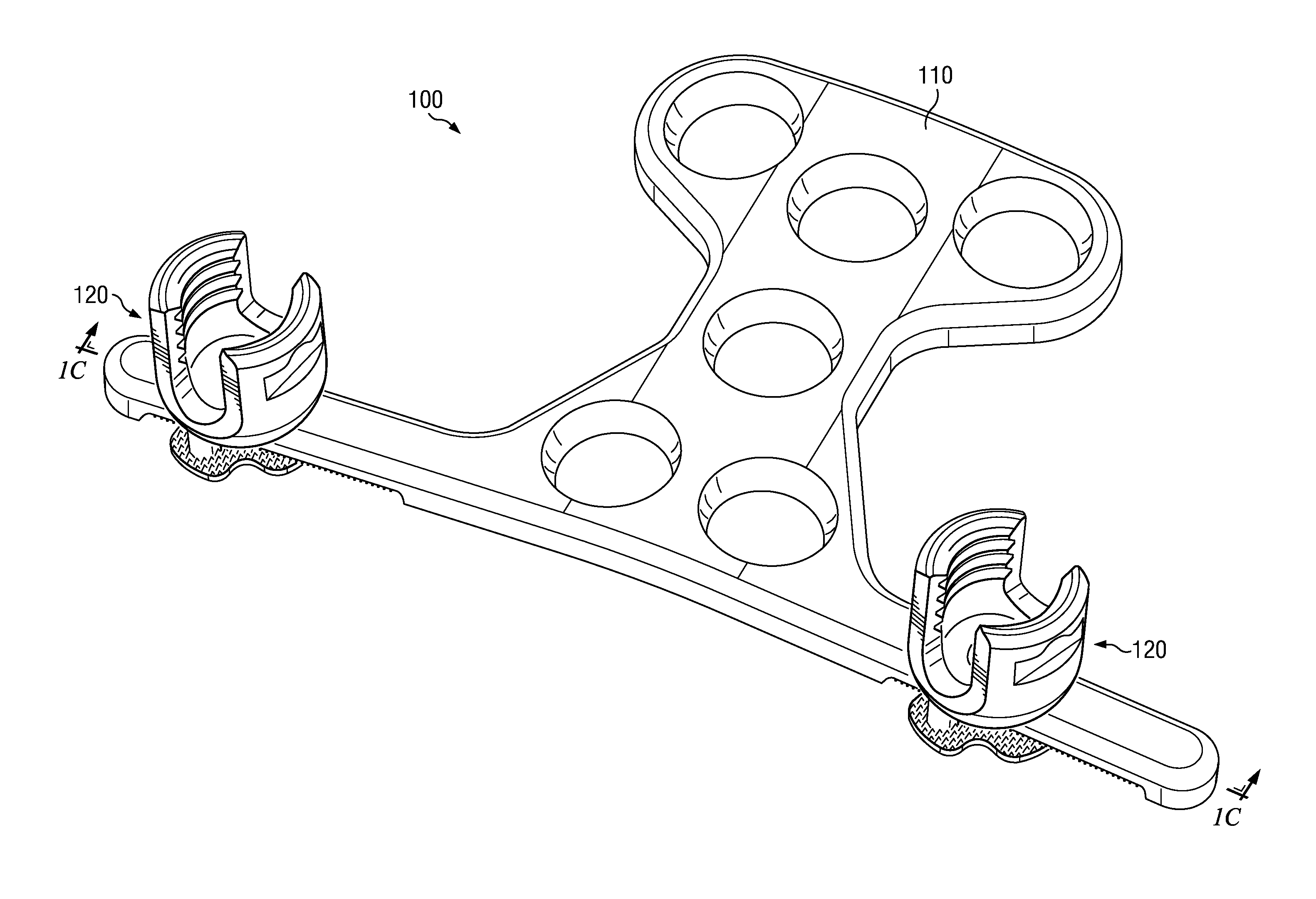
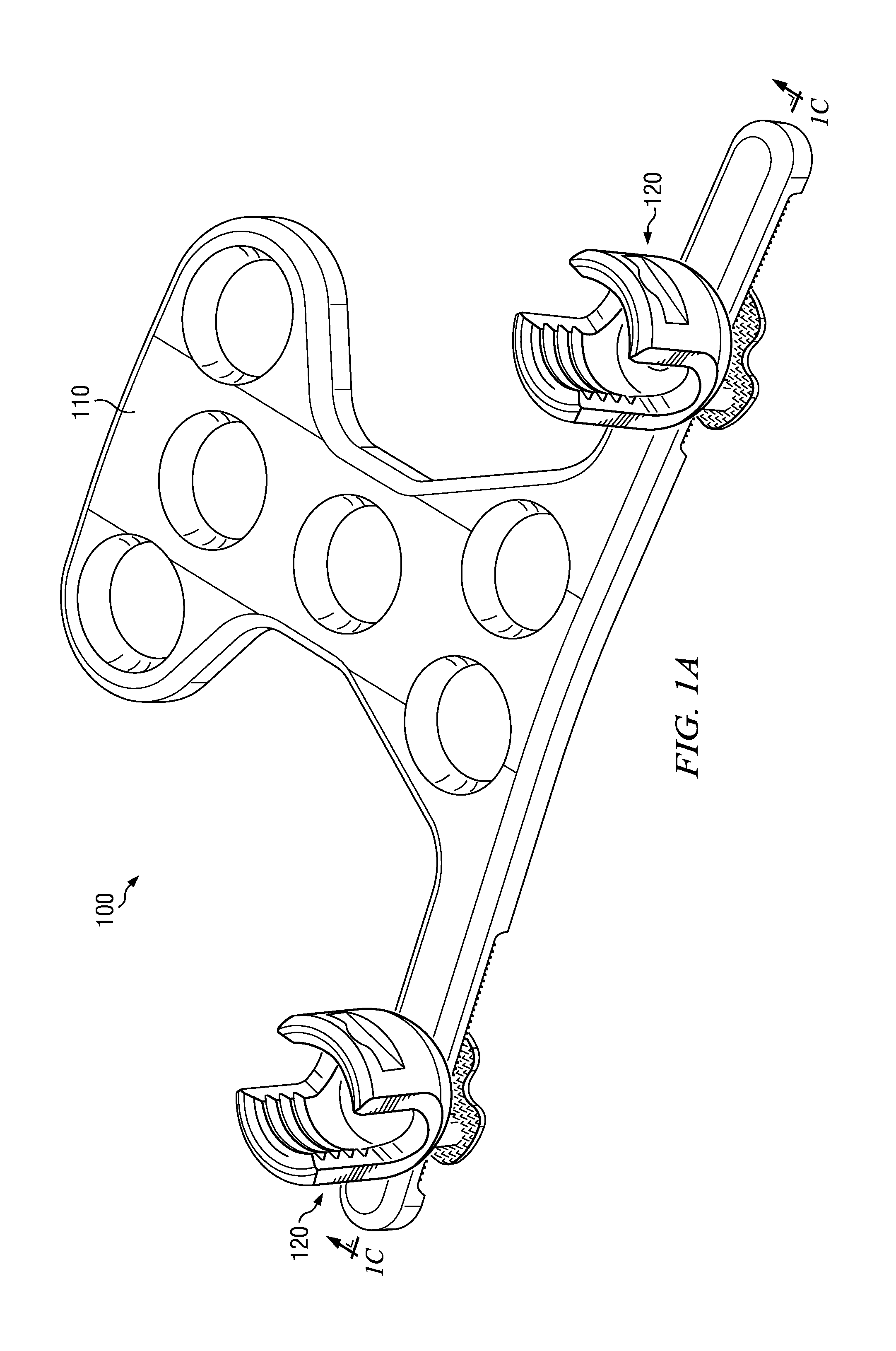
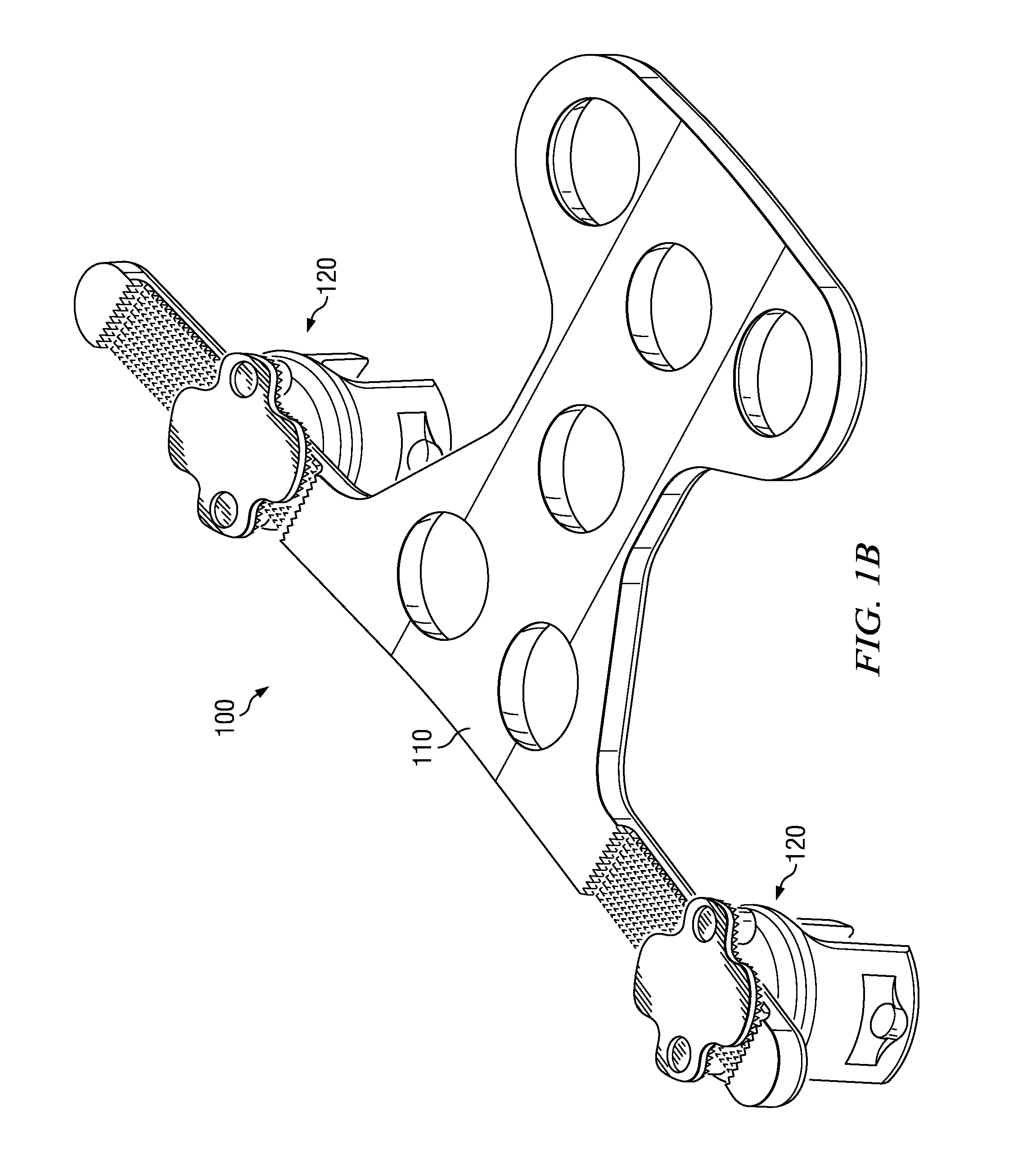
[0019]One embodiment of an implantable occipito-cervical fixation assembly 100 is illustrated in FIGS. 1A, 1B, and 1C. A top view of this embodiment is illustrated in FIG. 1A. A bottom view of this embodiment is illustrated in FIG. 1B. A cross-sectional view of this embodiment is illustrated in FIG. 1C. Occipital plate 110 supports one or more clamping assemblies 120. Although FIGS. 1A, 1B, and 1C illustrate embodiments with two clamping assemblies, embodiments with a single clamping assembly and embodiments with three or more clamping assemblies are contemplated. Occipital plate 110 may be secured to an occiput, and a stabilizing rod (not shown) may be secured in one or more clamping assemblies 120 to provide stabilization and / or promote fusion of the occipito-cervical junction.

[0020]Each clamping assembly 120 has at least two states: locked and unlocked. In its unlocked state, each clamping assembly 120 is movably attached to a portion of occipital plate 110, and may be adjusted p...


PUM


Abstract

An implantable orthopedic assembly comprises an occipital plate and one or more repositionable clamping assemblies for securing a stabilizing rod to the plate. When unlocked, the clamping assembly may be laterally and rotationally repositioned along a supporting rail. Locking occurs when a stabilizing rod is secured in the clamping assembly. The rod exerts a force upon a locking component, causing the locking component to exert a force upon the supporting rail. This force pulls a surface of the clamping assembly base into contact with the rail, effectively locking the clamping assembly base at a fixed position. The clamping assembly may further comprise a loading component to exert a stabilizing force on the locking component, keeping the clamping assembly positionally stable while adjustments are made prior to locking.

Description

TECHNICAL FIELD[0001]The disclosed embodiments relate generally to orthopedic implantable device technology, and more specifically to implantable devices for use in stabilizing the occipito-cervical junction and the cervical spine.BACKGROUND[0002]In the human body, the lower back portion of the skull is known as the occiput, and the neck vertebrae located closest to the skull are known as the cervical spine. Critical neurological and vascular structures descending from the brain into the spinal column pass through the junction between the skull and the cervical spine (the occipito-cervical junction). When disease or traumatic injury threatens the stability of the cervical spine and / or the occipito-cervical junction, surgical intervention may be required to protect these critical structures.[0003]Implantable occipito-cervical fixation systems that provide stabilization and / or promote fusion of the occipito-cervical junction are known in the art. However, existing systems may be diffi...

Claims


Application Information

Patent Timeline
Patent Type & Authority Patents(United States)
IPC IPC(8): A61B17/80
CPCA61B17/7055A61B17/88A61B17/7058
Inventor ZIOLO, TARATERMYNA, STEPHEN
Owner ORTHOFIX US LLC
Why Eureka
Try Eureka