

Hydrocarbon feed flexible high pressure nitration plant design
a high-pressure nitration and flexible technology, applied in the direction of chemistry apparatus and processes, separation processes, organic chemistry, etc., can solve the problems of high-pressure nitration complex and capital-intensive, and high-pressure nitration requires many expensive equipment pieces
- Summary
- Abstract
- Description
- Claims
- Application Information
AI Technical Summary
Problems solved by technology
Method used
Image

Examples
example 1
Nitration of Propane
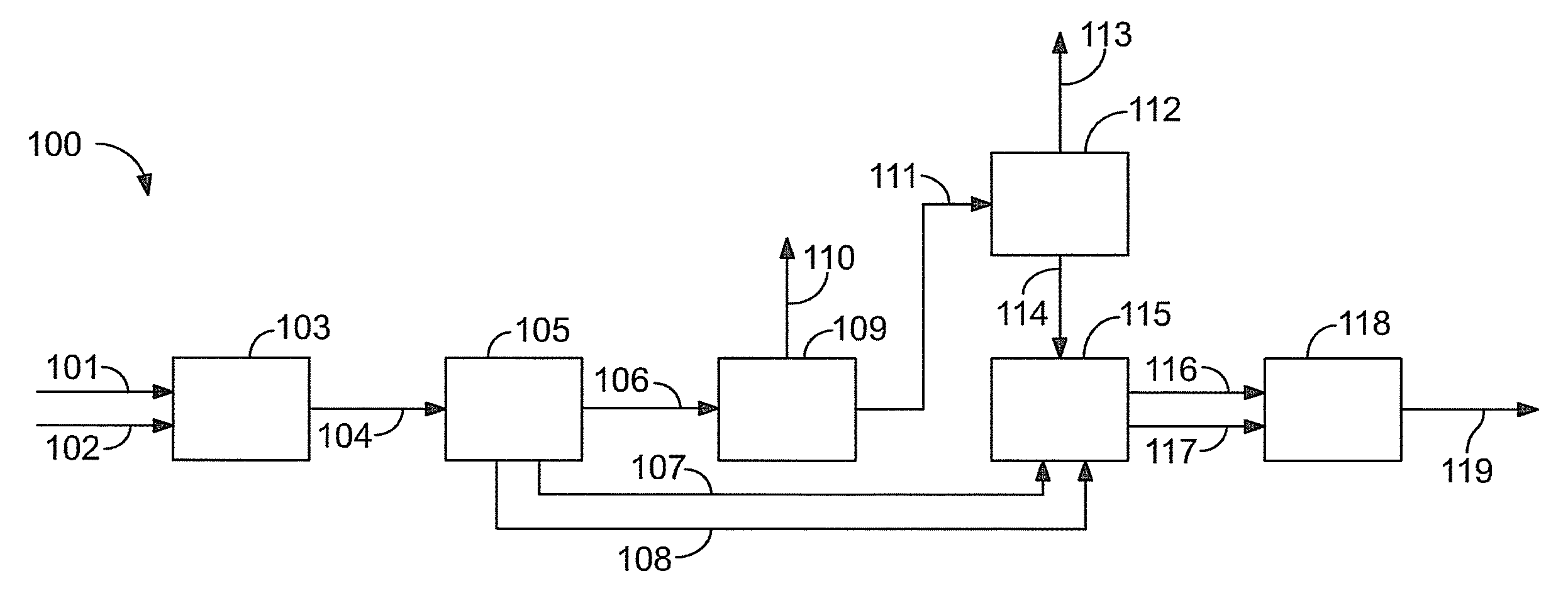
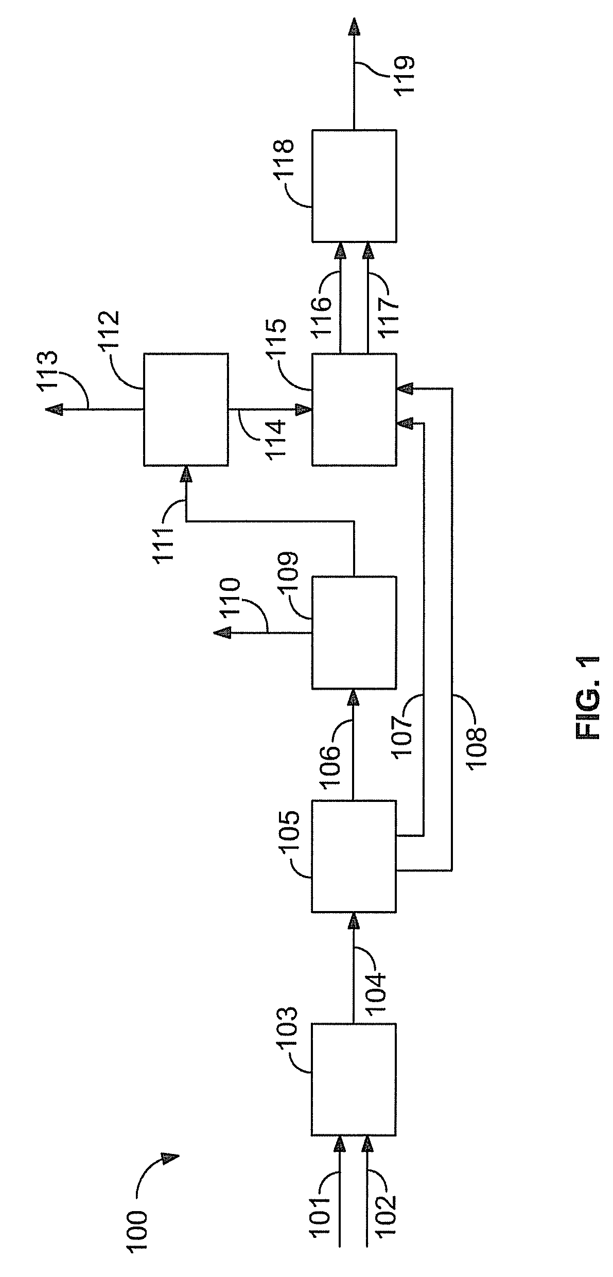
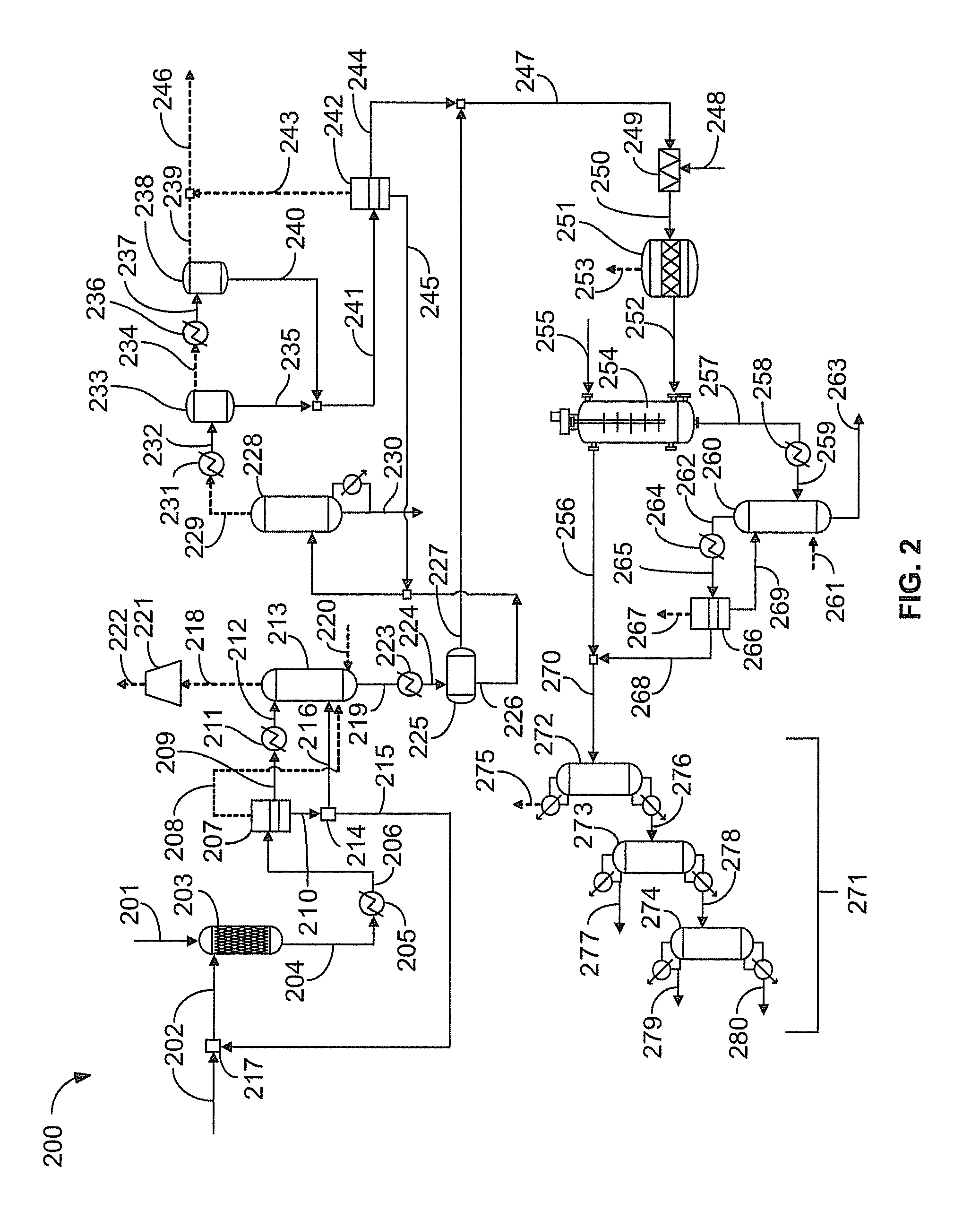
[0035]Propane is nitrated using about 30 weight percent dilute aqueous nitric acid as the nitrating agent at the following process conditions: about 1400 psig reactor pressure, about 230 degrees Celsius reactor temperature, a residence time of about 120 seconds, and a propane to nitric acid mole ratio of about 1.5:1. FIG. 2 illustrates an apparatus 200 for synthesizing nitropropane. A hydrocarbon feedstock 201 comprising propane and aqueous nitric acid 202 are introduced into a reactor 203 and react to form a reaction product stream 204. A composition of a typical reaction product stream 204 from the reactor 203 is summarized in Table 1.
[0036]
TABLE 1Reaction product stream composition for propane nitrationWeightComponentpercentlb / hWater68.746517Carbon monoxide0.9613Nitrogen0.5339Nitric oxide3.22134Nitrous oxide0.7449Propane13.59173Carbon dioxide1.71183Acetone0.2117Acetic acid1.81241Nitromethane0.162Nitroethane0.142Propionic acid0.21472-nitropropane7.550641-nitrop...
example 2
Nitration of Cyclohexane
[0045]In this example, ten cyclohexane nitration runs are carried out using 30% nitric acid and the effect of pressure, reactor temperature, and hydrocarbon to nitric acid mole ratio on yield and conversion is studied. Nitric acid conversions greater than 99% and cyclohexane conversion ranging from 20-40% can be achieved. The co-current downflow reactor designed for propane nitration is highly effective for nitrating cyclohexane.
[0046]Next, the hydrocarbon phase is washed with a sodium bicarbonate solution in order to neutralize any acidity. The hydrocarbon phase is neutralized and water-washed before stripping off cyclohexane in order to achieve quick and efficient hydrocarbon / aqueous phase separation.
[0047]Oil from the separator is fed to an 80 tray Karr® column with a variable drive unit to adjust mixing intensity. Deionized water is fed near the top of the column while the separated oil is fed near the bottom of the column.
[0048]Essentially the same manuf...
example 3
Nitration of Isobutane
[0060]Tert-nitrobutane is a potentially useful molecule that can be readily synthesized by high pressure nitration. Nitration of isobutane by high pressure nitration results in the formation of tert-nitrobutane with a selectivity of approximately 96%. The main nitrated byproducts are isomers of 1-nitro, 2-methylpropane. High nitric acid conversion (>95%) and isobutane conversion ranges from about 10 to 30% can be achieved.
[0061]The gaseous byproducts from the reaction are the usual nitration off-gases: CO, CO2, N2, N2O, and NO, in addition to liquid byproducts, which include nitroalcohols, nitro compounds, and oxidation byproducts such as tert-nitrobutane; 2-nitrobutane; 1-nitro, 2-methylpropane (an isomer of tert-nitrobutane); 2-nitro, 2-methyl, 1-propanol (NMP); 1-nitro,2-methyl,2-propanol; 1,2-dinitro,2-methyl propane, and acetic acid. In the laboratory, the liquid nitration product is readily phase separated into hydrocarbon and aqueous phases in a separato...
PUM
| Property | Measurement | Unit |
|---|---|---|
| pressure | aaaaa | aaaaa |
| temperature | aaaaa | aaaaa |
| temperature | aaaaa | aaaaa |
Abstract
Description
Claims
Application Information