Socket for electrical part

Active Publication Date: 2013-10-22
ENPLAS CORP
View PDF6 Cites 9 Cited by
  • Summary
  • Abstract
  • Description
  • Claims
  • Application Information

AI Technical Summary

Benefits of technology

[0015]According to the present invention, the floating plate is accommodated in a descended state when the socket is not yet mounted on the wiring substrate, e.g. while carrying the socket, and so the upper side contact portion can be surely inserted into the though hole of the floating plate even if the contact pin is too short. Therefore, different from the conventional art, the upper side contact portion of the contact pin is not possible to come off from the through hole of the floating plate during the socket is conveyed, and so no defect will occur even when the socket is used (e.g. when the floating plate moves vertically).
[0017]According to the feature, the lower terminal of the pin member is pressed by the wiring substrate and so the pin member is forcibly moved upward against the urging force of the first springs when the contact pin unit is mounted on the wiring substrate. As a result, the upper terminal of the pin member moves upward and so the floating plate is released from being held by the pin member, then, the floating plate becomes possible to move vertically under the state of being urged upward by the second spring. Thus, the pin member is pressed and the floating plate is released from holding only by mounting the contact pin unit on the wiring substrate, and so any particular operation is unnecessary for releasing the holding, consequently, providing satisfactory workability.

Problems solved by technology

Therefore, different from the conventional art, the upper side contact portion of the contact pin is not possible to come off from the through hole of the floating plate during the socket is conveyed, and so no defect will occur even when the socket is used (e.g. when the floating plate moves vertically).

Method used


Image

  • Socket for electrical part
  • Socket for electrical part
  • Socket for electrical part

Examples


Embodiment Construction

[0042]An preferred embodiment according to the present invention is described hereinafter.

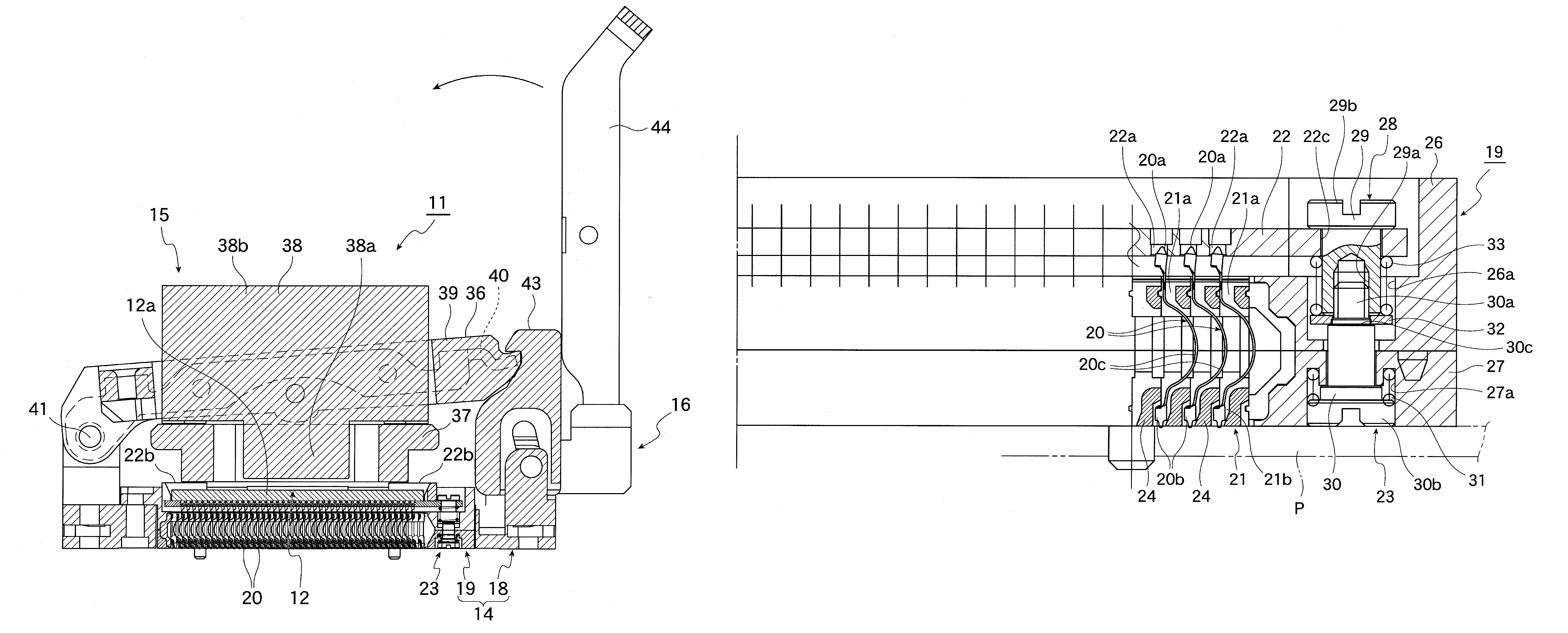
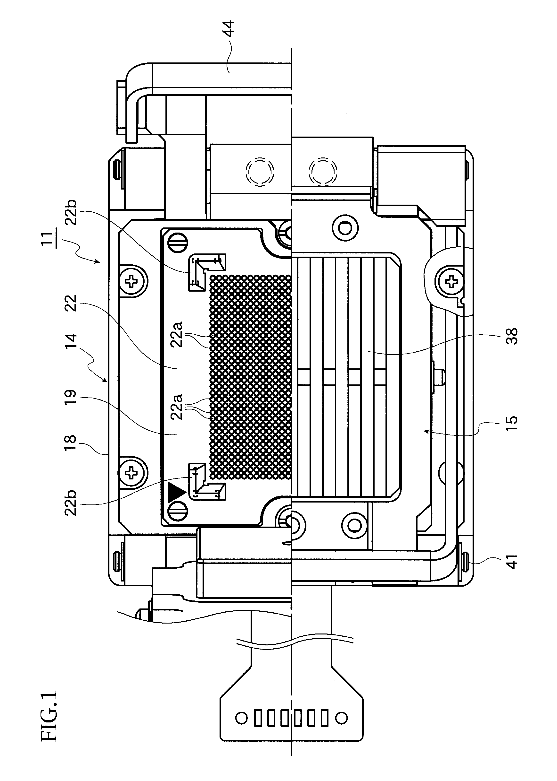
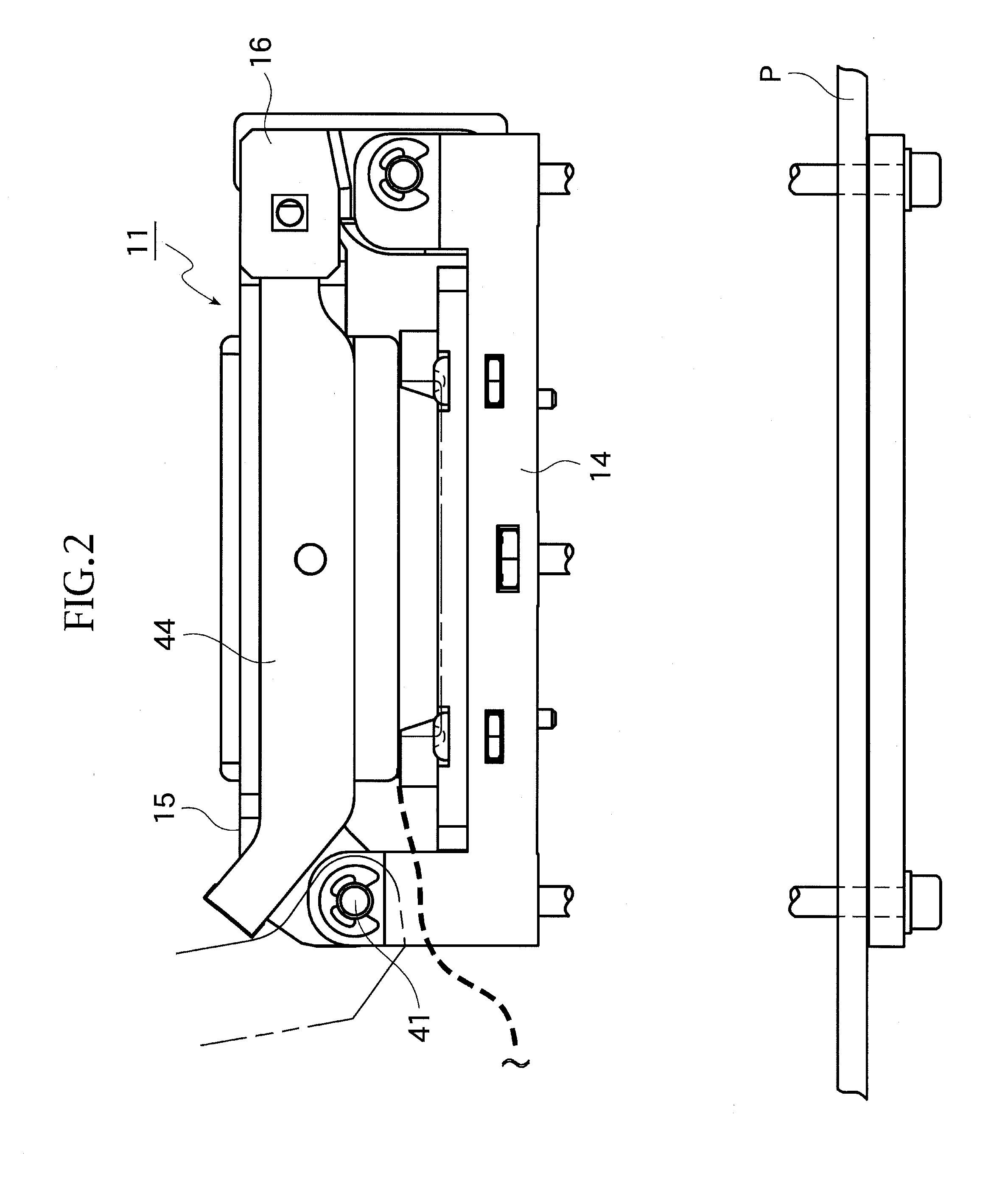
[0043]FIGS. 1 to 18C shows an embodiment of the present invention.

[0044]Firstly, the constitution of the present embodiment is described. In FIGS. 1 to 18C, the reference symbol 11 shows the IC socket as ‘socket for electrical part’. The IC socket 11 is constituted to be mounted on the wiring substrate P. The IC package 12 is used to electrically connect the spherical terminals 12b as ‘terminal’ of the IC package 12 and the wiring substrate P to perform burn-in-test etc. of the IC package as an ‘electrical part’.

[0045]As shown in FIG. 18A to 18C, the IC package 12 comprises the package body 12a, the planar view of which is quadrangle. A matrix of plural spherical terminals 12b as ‘terminal’ are formed so as to project from the lower surface of the package body 12a.

[0046]Incidentally, as shown in FIG. 1, 2 and so on, the IC socket 11 is fixed on the wiring substrate P, and comprises the socket ...


PUM


Abstract

A socket for electrical part mounted on the wiring substrate to accommodate an electrical part. The present invention comprises a socket body, a floating plate and a holding structure. The socket body has a contact pin unit comprising a unit body in which the plural contact pins are mounted. The floating plate is mounted on upper side of the unit body to accommodate the electrical part, and comprises through holes into which the upper side contact portions of contact pins are inserted. The holding structure holds the floating plate in a descended state when the socket for the electrical part is not yet mounted on the wiring substrate, and releases the holding state of floating plate and makes the floating plate to be capable of moving vertically under the state of being urged upward when the socket for the electrical part is mounted on the wiring substrate.

Description

BACKGROUND OF THE INVENTION[0001]1. Field of the Invention[0002]The present invention relates to a socket for an electrical part which is mounted on a wiring substrate and accommodates an electrical part such as a semiconductor device (hereinafter called “IC package”) for performing a test of the electrical part, for example.[0003]2. Description of the Prior Art[0004]In a known art, there has been provided an IC socket as “a socket for an electrical part” for accommodating and detachably holding an IC package as an “electrical part” (see Japanese patent Gazette No. 3566691).[0005]The IC package comprises a package body (i.e. an electrical part body), the shape of which is a square for example, and the package body is provided with the terminals.[0006]On the other hand, the IC socket comprises a socket body which is mounted on a wiring substrate, and the socket body comprises a contact pin unit provided with plural contact pins for electrically connecting the terminals of the IC pack...

Claims


Application Information

Patent Timeline
Patent Type & Authority Patents(United States)
IPC IPC(8): H01R13/62
CPCG01R1/0466H01R13/62933H01R12/714G01R31/2863
Inventor YOKOYAMA, YUJI
Owner ENPLAS CORP
Why Eureka
Try Eureka