Liquid ejecting head and liquid ejecting apparatus

a liquid ejecting head and liquid ejecting technology, applied in the direction of printing, inking apparatus, etc., can solve the problems of unnecessary vibration and fluctuations in ejecting properties, and achieve the effect of suppressing unnecessary vibration

Active Publication Date: 2013-10-29
SEIKO EPSON CORP
View PDF8 Cites 2 Cited by
  • Summary
  • Abstract
  • Description
  • Claims
  • Application Information

AI Technical Summary

Benefits of technology

[0010]It is an advantage of some aspects of the invention to provide a liquid ejecting head and a liquid ejecting apparatus capable of ejecting a liquid in a stable manner, regardless of the driving frequency, while suppressing unnecessary vibrations arising due to the ejection of the liquid.
[0012]According to this configuration, it is difficult for fluctuations in the unique vibration cycle Tc caused by the ejection of the liquid to occur, and it is thus possible to suppress fluctuations in the frequency properties, such as the weight of the liquid ejected through the nozzles (or the flight speed) based on the unique vibration cycle Tc. As a result, it is possible to eject the liquid in a stable manner, from a low-frequency range (several kHz) to a high-frequency range (several tens of kHz). Furthermore, because it is difficult for unnecessary vibrations to occur, the liquid can be ejected at a higher frequency, which can contribute to higher-frequency driving. Particularly, in the case where the viscosity of the liquid is high (for example, a viscosity of more than 6 mPa·s at ejection), it is possible to eject the liquid in a stable manner while suppressing an insufficient supply of liquid from the common liquid chamber to the pressure chambers through the ink supply channels.
[0014]According to this configuration, it is easy for the liquid to flow toward the nozzles when a pressure fluctuation has been imparted on the pressure chambers. As a result, it is possible to efficiently eject the liquid from the nozzles.
[0016]According to this configuration, it is possible to further suppress vibrations in the meniscus and obtain more flat frequency properties.

Problems solved by technology

In other words, if the time between a given liquid ejection and the subsequent liquid ejection is reduced, the subsequent ejection will be carried out before vibrations in the liquid within pressure chambers including the nozzles (and in particular, in the meniscuses) immediately after the previous ejection have sufficiently converged, and such differences in the meniscus states will result in fluctuations in the ejection properties.
It should be noted that these problems are not limited to ink jet recording apparatuses, and are also present in other liquid ejecting apparatuses that eject liquids aside from ink.
Furthermore, because it is difficult for unnecessary vibrations to occur, the liquid can be ejected at a higher frequency, which can contribute to higher-frequency driving.

Method used


Image

  • Liquid ejecting head and liquid ejecting apparatus
  • Liquid ejecting head and liquid ejecting apparatus
  • Liquid ejecting head and liquid ejecting apparatus

Examples


Embodiment Construction

[0027]Hereinafter, an embodiment of the invention will be described with reference to the appended drawings. Although various limitations are made in the embodiment described hereinafter in order to illustrate a specific preferred example of the invention, it should be noted that the scope of the invention is not intended to be limited to this embodiment unless such limitations are explicitly mentioned hereinafter. An ink jet recording apparatus (referred to as a “printer”) will be given hereinafter as an example of a liquid ejecting apparatus according to the invention.

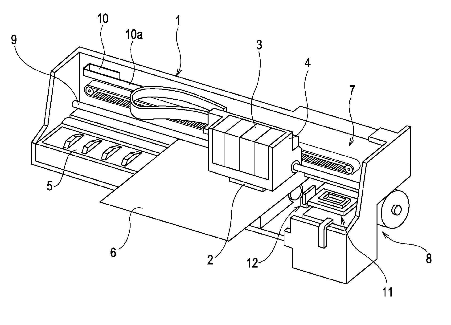
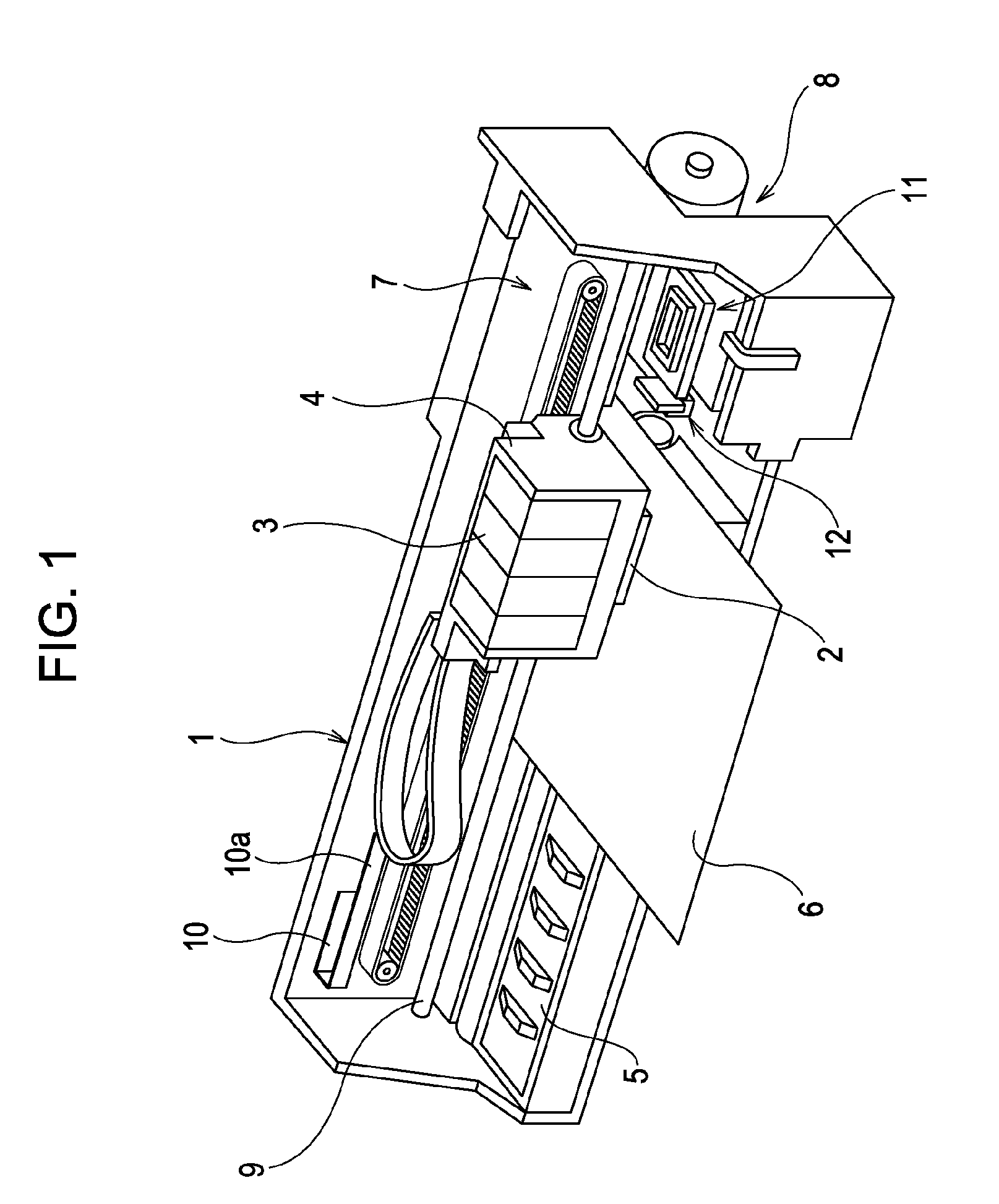
[0028]FIG. 1 is a perspective view illustrating the configuration of a printer 1. The printer 1 illustrated as an example here is configured so as to record images, text, or the like onto a recording medium by ejecting ink, which is a type of liquid, toward the recording medium (landing target), which is recording paper, film, or the like. This printer 1 includes: a carriage 4, in which a recording head 2 serving as ...


PUM


Abstract

The dimensions / shape of ink flow channels in a recording head are designed so that when the inertance of nozzles is represented by Mn, the inertance of the ink supply channels is represented by Ms, the combined resistance obtained by combining the flow channel resistance in the nozzles, the flow channel resistance in pressure chambers, and the flow channel resistance in the supply channels is represented by R, and a unique vibration cycle of the pressure fluctuation arising in the ink within the pressure chambers is represented by Tc, the following Equation (A) holds true.√{square root over (MnMs)}≦RTc  (A)

Description

BACKGROUND[0001]1. Technical Field[0002]The present invention relates to liquid ejecting heads provided in liquid ejecting apparatuses such as ink jet printers and to liquid ejecting apparatuses provided therewith, and particularly relates to liquid ejecting heads and liquid ejecting apparatuses capable of suppressing unnecessary vibrations occurring when ejecting a liquid.[0003]2. Related Art[0004]A liquid ejecting apparatus is an apparatus that includes an ejecting head, and that ejects various types of liquid from this ejecting head. Image recording apparatuses such as ink jet printers, ink jet plotters, and so on can be given as examples of such a liquid ejecting apparatus, but recently, such technology is also being applied in various types of manufacturing apparatuses that exploit an advantage in which extremely small amounts of liquid can be caused to land in predetermined positions in a precise manner. For example, such technology is being applied in display manufacturing ap...

Claims


Application Information

Patent Timeline
Patent Type & Authority Patents(United States)
IPC IPC(8): B41J2/04B41J2/16B41J2/14B41J2/05
CPCB41J2/14274B41J2202/11
Inventor OZAWA, KINYA
Owner SEIKO EPSON CORP
Why Eureka
Try Eureka