HE-3 tube array alignment mount

Active Publication Date: 2013-10-29
BAKER HUGHES INC
View PDF6 Cites 3 Cited by
  • Summary
  • Abstract
  • Description
  • Claims
  • Application Information

AI Technical Summary

Problems solved by technology

However, it should be appreciated that the support frame and / or the detector tubes / packs may have aspects that cause some difficulty in obtaining the goal of having all of the tubes extend with their respective elongate center axes being located within a single plane.

Method used


Image

  • HE-3 tube array alignment mount
  • HE-3 tube array alignment mount
  • HE-3 tube array alignment mount

Examples


Embodiment Construction

[0014]Example embodiments that incorporate one or more aspects of the invention are described and illustrated in the drawings. These illustrated examples are not intended to be a limitation on the invention. For example, one or more aspects of the invention can be utilized in other embodiments and even other types of devices. Moreover, certain terminology is used herein for convenience only and is not to be taken as a limitation on the invention. Still further, in the drawings, the same reference numerals are employed for designating the same elements.

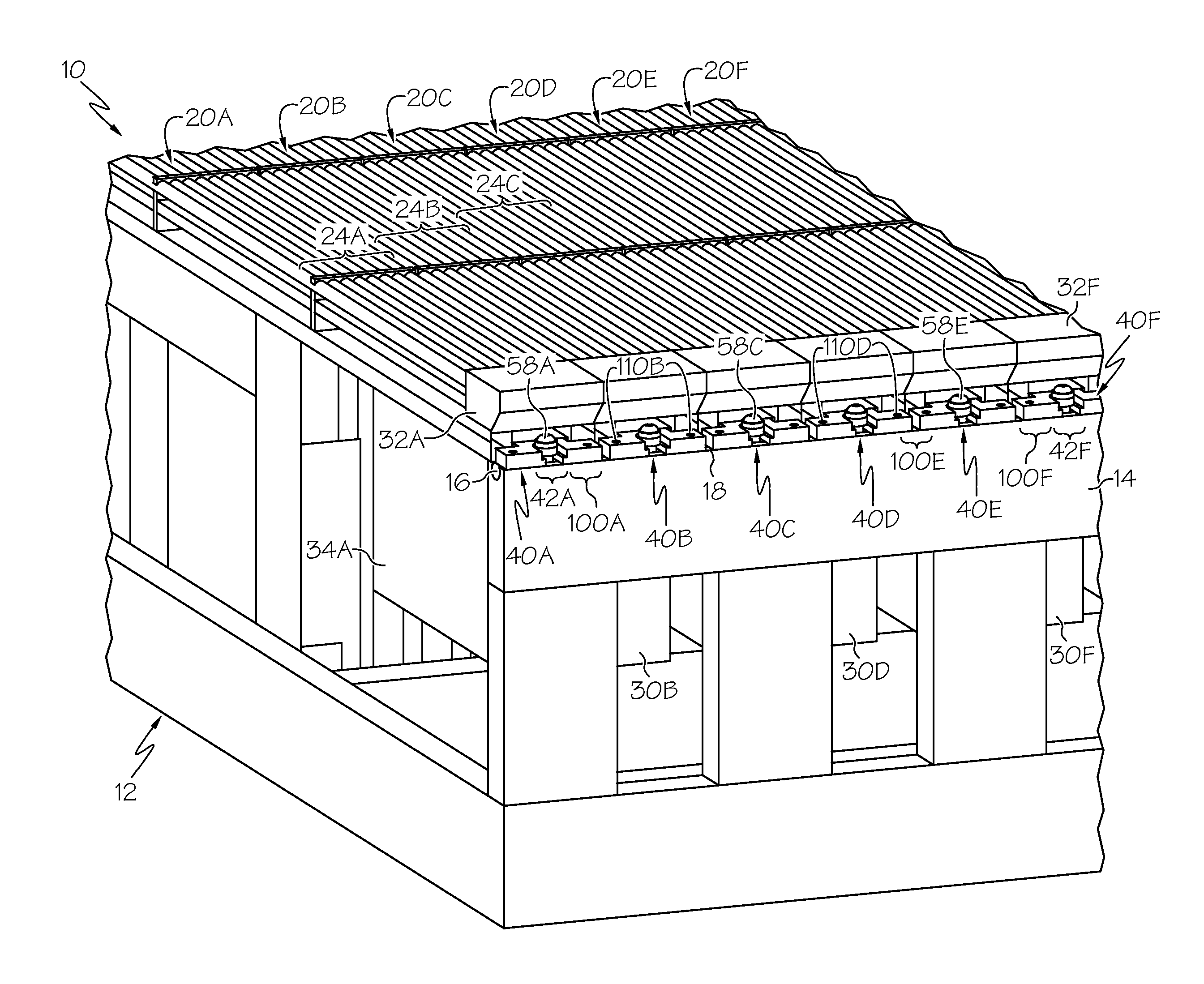
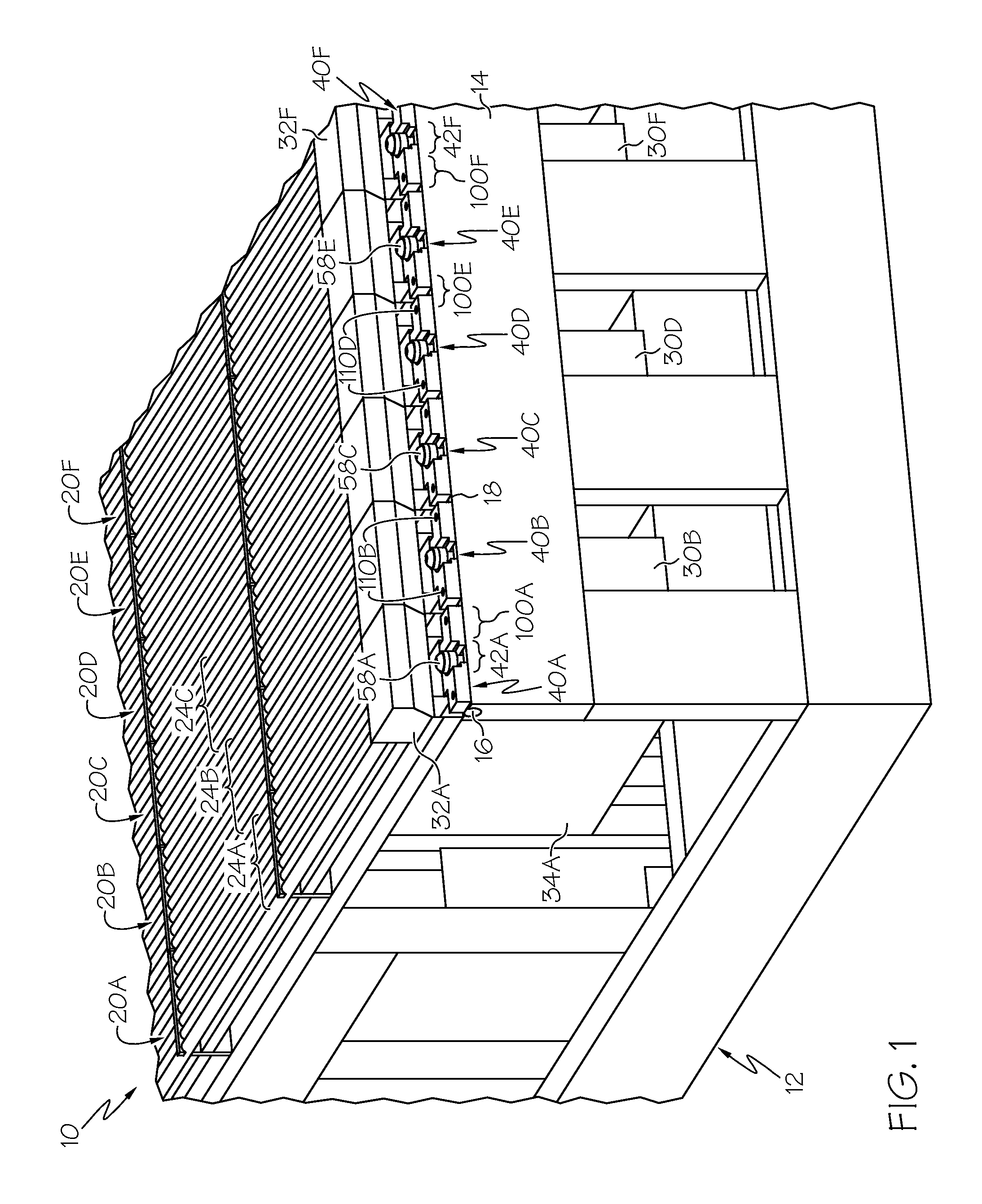
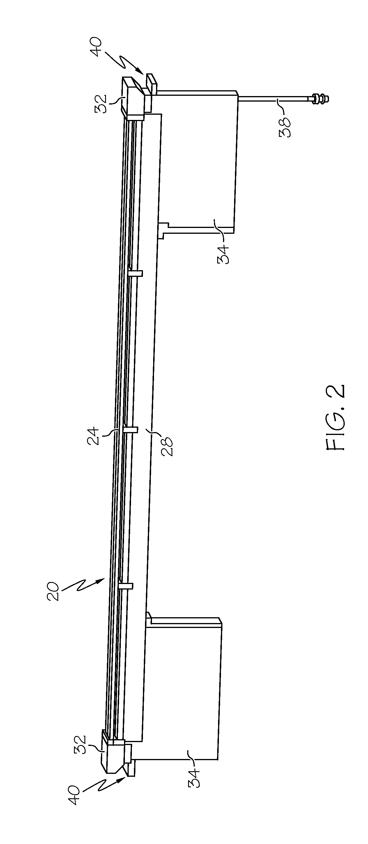
[0015]An example of an arrangement 10 for detecting energy particle impingement in accordance with an aspect of the present invention is shown within FIG. 1. The example arrangement 10 includes a support frame 12. The specific example of the support frame 12 shown within FIG. 2 should not be considered to be a limitation upon the present invention and variations and modifications of the support frame are certainly contemplated. With su...


PUM


Abstract

An arrangement for detecting energy particle impingement includes a support frame and a multi-tube detector pack. Each pack includes multiple detector tubes. Each tube contains at least one sensitive material. Each tube is elongate along a respective axis. The tubes extend parallel with the respective axes being co-planar. Each pack includes mounting tabs located at each axial end. The tabs provide support for the tubes within the pack. At least one of the tabs has at least one securing portion and at least one adjusting portion. Each pack includes at least one operable securing member extending from the respective securing portion to the frame. Operation of the securing member secures the pack to the support frame. Each pack includes at least one operable adjusting member extending from the respective adjusting portion to the frame. Operation of the adjusting member changes an orientation of the pack.

Description

BACKGROUND OF THE INVENTION[0001]1. Field of the Invention[0002]The invention relates to a detector array having a plurality of detector tubes, and specifically relates to an alignment mount for changing orientation of the plurality of detector tubes.[0003]2. Discussion of Prior Art[0004]A scattering detector arrangement includes a target upon which an energy particle, such as a Neutron, impinges and proceeds therefrom as a “scatter.” The arrangement also includes a plurality of detector tubes positioned across an area for receipt of the scattered energy particle (e.g., a scattered Neutron). The plurality of tubes are operatively connected to sensory and / or processing equipment, circuitry or the like. Various properties, characteristics, and other information can be discerned by the scatter impingement location on the detector tubes.[0005]As can be appreciated, the plurality of detector tubes is supported by some type of support structure that can be generically referred to as a sup...

Claims


Application Information

Patent Timeline
Patent Type & Authority Patents(United States)
IPC IPC(8): G01T3/00
CPCG01T3/008H01J47/00G01T1/18H01J47/06H01J47/1222H01J47/125
Inventor BAUS, EDWARD JOSEPHAUSTIN, RANDY DIXON
Owner BAKER HUGHES INC
Why Eureka
Try Eureka