Systems and methods involving graphically displaying control systems

a control system and graphic display technology, applied in the field of graphic display of control system logic, can solve the problem that the logic process of the display function block logic process cannot be graphically provided for analyzing the system, and achieve the effect of providing a detailed view of the logic process desired for the analysis of the system

Active Publication Date: 2013-10-29
GENERAL ELECTRIC CO
View PDF11 Cites 2 Cited by
  • Summary
  • Abstract
  • Description
  • Claims
  • Application Information

AI Technical Summary

Problems solved by technology

Existing GUIs that display function block logic processes fail to graphically provide a detailed view of the logic process desired for analyzing the system.

Method used


Image

  • Systems and methods involving graphically displaying control systems
  • Systems and methods involving graphically displaying control systems
  • Systems and methods involving graphically displaying control systems

Examples


Embodiment Construction

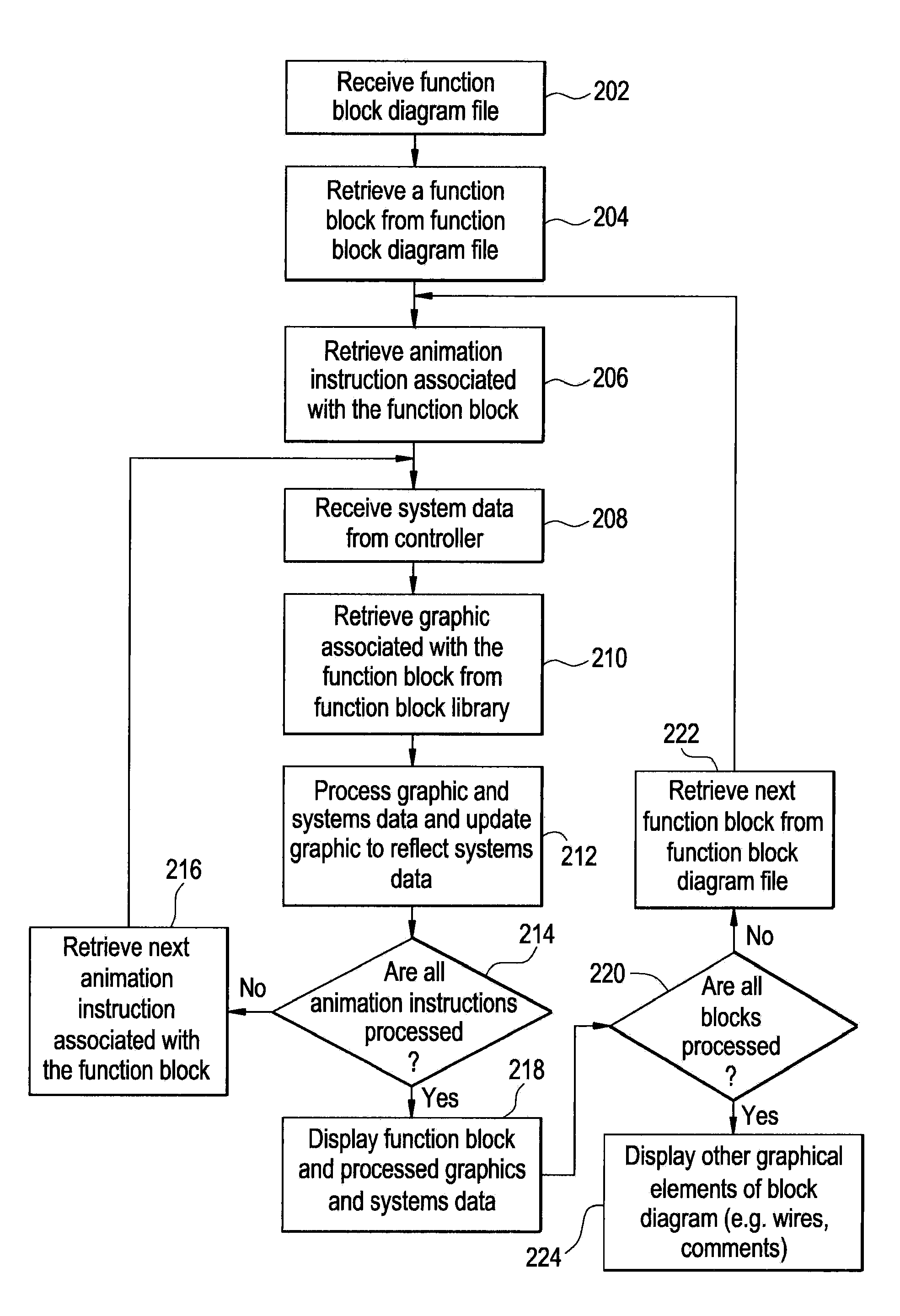
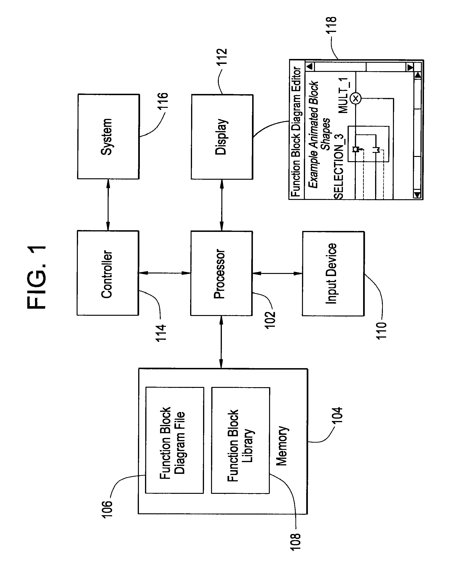
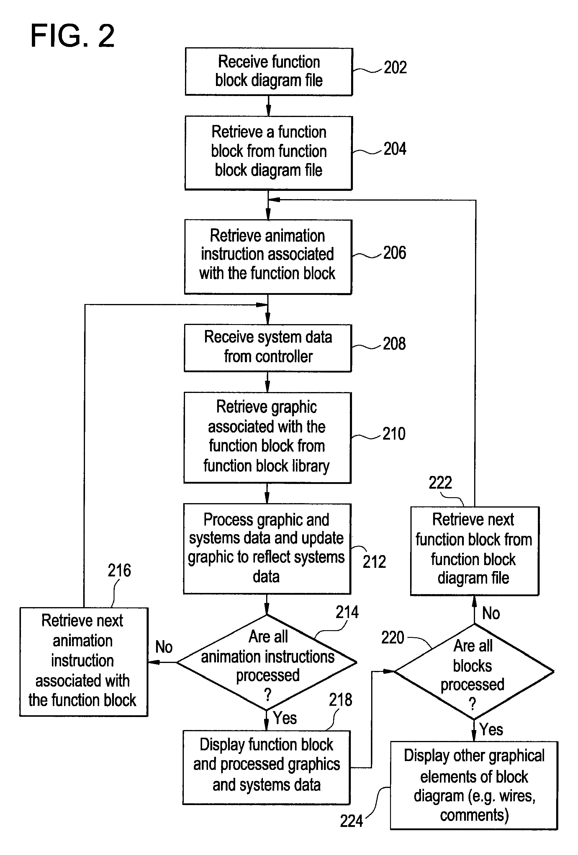
[0013]Graphical user interfaces (GUI) may be used to design and operate control systems. For example, a function block editor application may be used to graphically design and display function block diagrams. Function block diagrams are used to graphically display control system functions. Function block diagrams include function blocks that perform logic functions in a control system. The input and output pins of function blocks are connected with lines (wires) that input and output signals from the function blocks in the control system.

[0014]Once a control system has been designed using a function block editor application, the graphical representation of the control system logic may be compiled and processed in a controller that controls a system. For example, electrical power systems are controlled by a controller that receives signals from sensors in the electrical power system, and processes the signals using the control system logic, and issues control signals to the electrica...


PUM


Abstract

A method for displaying a control system comprising, receiving a function block diagram file including a function block having an associated logic function, receiving an animation instruction associated with the function block, receiving system data from a system controller, receiving a first graphic associated with the logic function from a function block library, processing the first graphic and the system data according to the animation instruction to render an updated first graphic reflecting the systems data, and displaying the function block and the rendered updated first graphic associated with the logic function.

Description

BACKGROUND OF THE INVENTION[0001]The subject matter disclosed herein relates to control system logic displayed using a graphical user interface (GUI) that presents logic functions and paths using function blocks and path connector lines. The function blocks include input pins that receive signals. The function blocks perform a defined logic function and output the results of the logic function with output pins. The input and output pins of function blocks are connected by path connectors lines (wires) to complete the system logic.[0002]The GUI is used to design control system logic functions that may be compiled and used in processors that control real world systems such as, for example, electrical power systems that include electrical generators. One advantage of using a GUI to display control systems logic is that the control system logic functions may be displayed to a user or technician while a system is operating in real time. The display of the connected function blocks allows...

Claims


Application Information

Patent Timeline
Patent Type & Authority Patents(United States)
IPC IPC(8): G06T13/00G06F3/048
CPCG05B19/0426G05B2219/23258G05B19/056G06F30/33
Inventor GRUBBS, ROBERT WILLIAMDEMAURICE, ANDRE STEVENDEVGAN, ASHISH VIJAY
Owner GENERAL ELECTRIC CO
Why Eureka
Try Eureka