Server system with direct current transformation units receiving power on signal and generating operating voltage and ready signal

a technology of transformer unit and server system, which is applied in the field of server system, can solve the problems of increasing reducing the efficiency of the server system, and achieve the effect of reducing the circuit cost of the server system

Inactive Publication Date: 2013-11-05
INVENTEC CORP
View PDF11 Cites 1 Cited by
  • Summary
  • Abstract
  • Description
  • Claims
  • Application Information

AI Technical Summary

Benefits of technology

[0007]The invention is directed to a server system, in which a direct current (DC) transformation unit is used to replace a conventional power supply for supplying power, so as to reduce a circuit cost of the server system. Moreover, the DC transformation unit has an indicating lamp to indicate an operation state of the DC transformation unit.
[0021]According to the above descriptions, in the invention, the DC transformation units are used to replace the conventional power supply for supplying power, and all of the DC transformation units can share one AC to DC transformer, so that the circuit cost is reduced. Moreover, the first protection circuit, the second protection circuit and the voltage detection module of the DC transformation unit can be used to detect the standby voltage, the standby voltage ready signal, the operating voltage and the operating voltage ready signal, and display a detecting result on the display unit. In this way, a user can quickly know whether the standby voltage and the operating voltage are in an unstable state (for example, an over current state, an over voltage state or an under voltage state), so as to carry on maintenance.

Problems solved by technology

Therefore, efficiency of the server system is reduced, and circuit cost of the server system is increased.

Method used


Image

  • Server system with direct current transformation units receiving power on signal and generating operating voltage and ready signal
  • Server system with direct current transformation units receiving power on signal and generating operating voltage and ready signal
  • Server system with direct current transformation units receiving power on signal and generating operating voltage and ready signal

Examples


Embodiment Construction

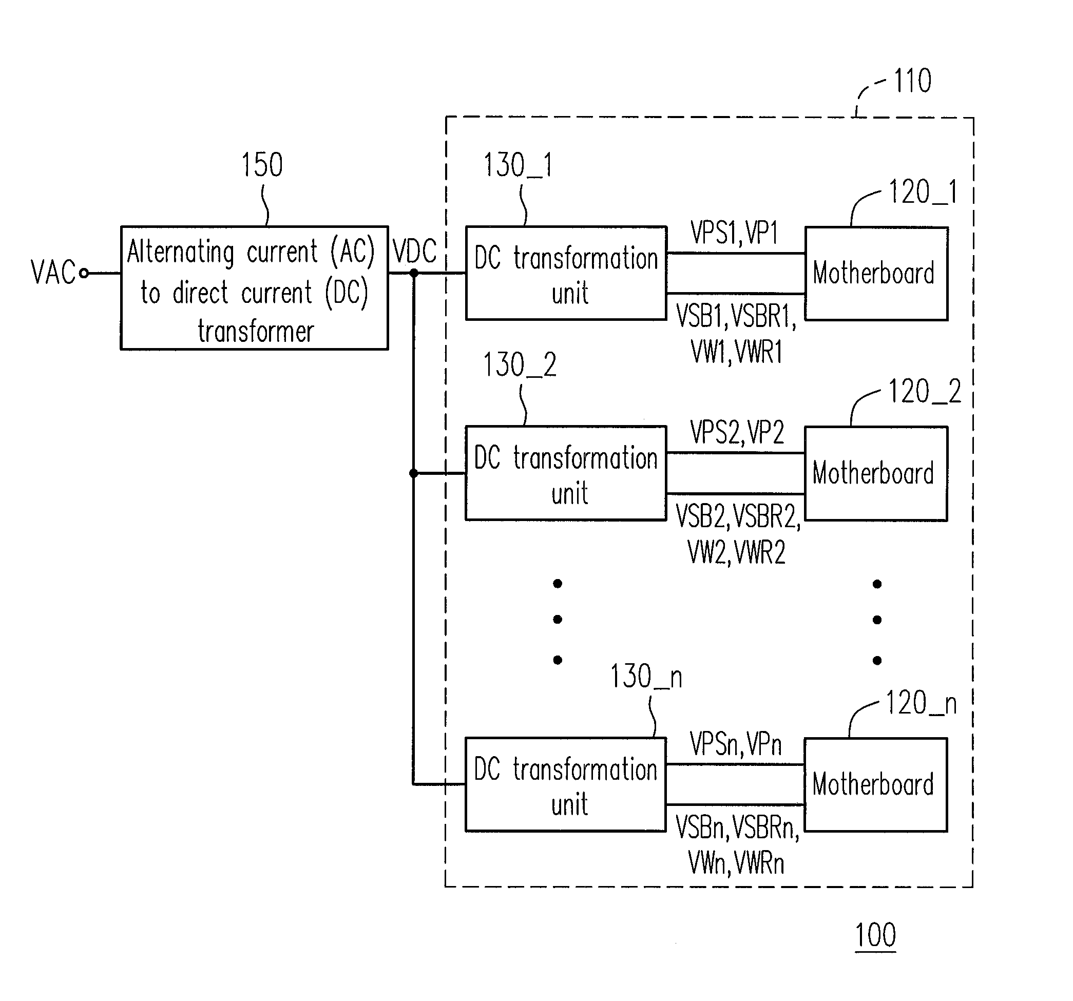
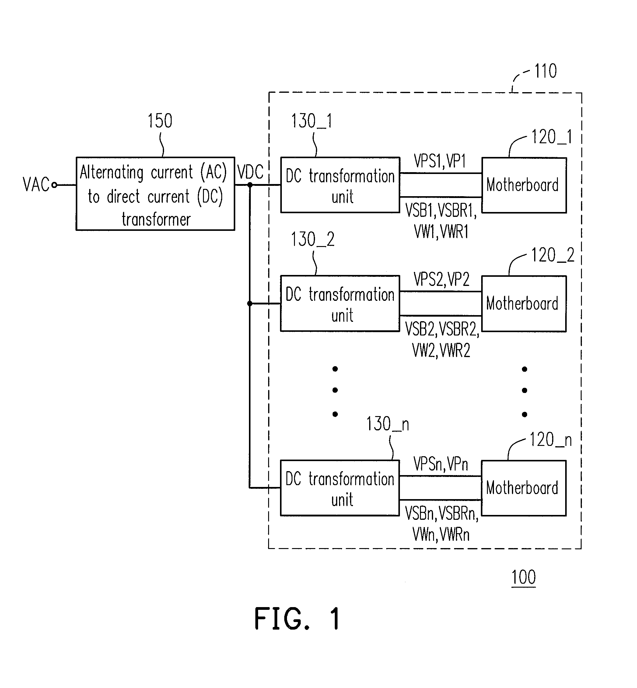
[0030]FIG. 1 is a block diagram of a server system according to an embodiment of the invention. The server system 100 of the present embodiment is adapted to receive a direct current (DC) voltage VDC sent by an alternating current (AC) to DC transformer 150, where the AC to DC transformer 150, for example, receives an AC voltage VAC (for example, 100V-230V), and transforms the AC voltage VAC to generate the DC voltage VDC (for example, 12V). Referring to FIG. 1, the server system 100 includes a rack 110, a plurality of motherboards 120_1-120—n and a plurality of DC transformation units 130_1-130—n, where n is a positive integer greater than 1.

[0031]The motherboards 120_1-120—n are respectively inserted on the rack 110, and generate power on signals VPS1-VPSn when the motherboards 120_1-120—n are turned on, so as to indicate whether the motherboards 120_1-120—n are in operation. The DC transformation units 130_1-130—n are respectively disposed on the rack 110, and each of the DC tran...


PUM


Abstract

A server system including a rack, motherboards and direct current (DC) transformation units is provided. Each of the motherboards is inserted on the rack, and generates a power on signal. Each of the DC transformation units is on the rack and receives a DC voltage. When each of the motherboards is electrically connect to the corresponding DC transformation unit, each of the DC transformation units generates a standby voltage and a standby voltage ready signal to the motherboard according to the DC voltage so that the motherboard enters a standby state according to the standby voltage ready signal. When the motherboard corresponding to each of the DC transformation unit generates the power on signal, the DC transformation unit receives the power on signal and generates an operating voltage and an operating voltage ready signal to the motherboard, and the motherboard is turned on according to the operating voltage ready signal.

Description

CROSS-REFERENCE TO RELATED APPLICATION[0001]This application claims the priority benefit of Taiwan application serial no. 99141267, filed on Nov. 29, 2010. The entirety of the above-mentioned patent application is hereby incorporated by reference herein and made a part of this specification.BACKGROUND[0002]1. Field of the Invention[0003]The invention relates to a server system. Particularly, the invention relates to a server system having a direct current transformation unit and a voltage protection display function.[0004]2. Description of Related Art[0005]Generally, a power supply is used to supply an operating voltage for a server system. The current power supply generally receives an alternating current (AC) voltage of 100V-230V first, and then a transformer inside the power supply transforms the AC voltage into a direct current (DC) voltage. Then, the power supply transforms the DC voltage into a voltage of 12V, 5V or 3V to serve as the operating voltage of the server system.[00...

Claims


Application Information

Patent Timeline
Patent Type & Authority Patents(United States)
IPC IPC(8): G06F1/26
CPCG06F1/26G06F1/3296Y02B60/1285Y02B60/32Y02D10/00Y02D30/50
Inventor YANG, JUN-DONG
Owner INVENTEC CORP
Why Eureka
Try Eureka