Cutting insert, cutting tool using the same, and cutting method

a cutting tool and cutting insert technology, applied in the direction of shaping cutters, manufacturing tools, wood boring tools, etc., can solve the problems of large cutting force of the cutting insert b>101/b> thus constructed, high vibration, and easy chipping of the cutting edge, so as to reduce the occurrence of vibration during cutting, and reduce the effect of vibration

Active Publication Date: 2013-11-12
KYOCERA CORP
View PDF18 Cites 5 Cited by
  • Summary
  • Abstract
  • Description
  • Claims
  • Application Information

AI Technical Summary

Benefits of technology

[0008]An advantage of the invention is to provide a cutting insert and a cutting tool using the cutting insert as well as a cutting method, which are capable of reducing the occurrences of vibration during cutting, and chipping.
[0009]Other advantage of the invention is to provide a cutting insert and a cutting tool using the cutting insert as well as a cutting method, which have a small cutting force and excellent cutting performance.Means for Solving the Problems
[0010]In order to solve the above problem, the present inventor carried out intensive consideration to find the following finding. That is, among the above-mentioned cutting edges of the cutting insert 101, the flat cutting edge 105 located near to the tip end of the holder 111 is for retaining the strength of the high-positioned corner cutting edge 104 that is used for cutting all the times. The flat cutting edge 105 requires sufficient strength because the flat cutting edge 105 comes in first contact with a work material in the cutting edge during cutting. Therefore, the flat cutting edge 105 has a substantially the same height as the high-positioned corner cutting edge 104 for achieving compatibility between retention of the sufficient strength and retention of the cutting edge angle.
[0011]On the other hand, the arrangement of the tilted cutting edge 107 enables the cutting insert 101 itself to have an axial rake angle. Therefore, cutting properties can be improved and cutting force can be reduced without ensuring a large axial rake angle added to the holder 111 itself when the cutting insert 101 is mounted on the holder 111. This ensures the thickness of the holder 111 located below the bottom surface of the cutting insert 101, thus retaining the rigidity of the holder 111.
[0012]However, when the cutting edge is thus constructed, the cutting edge angle is changed in the middle of the cutting edge, namely, the cutting edge has an intersection “a” where the cutting edge angle is changed, at the intersection of the flat cutting edge 105 with the tilted cutting edge 107 (refer to FIG. 16(b)). The intersection “a” is susceptible to stress during cutting. With the intersection “a” as a starting point, vibration is likely to occur during cutting, and a chipping is likely to occur.
[0013]In this case, cutting force can be reduced by forming a specific groove at a flank 103. Alternatively, the stress concentrated at the intersection “a” during cutting can be reduced by forming at least one groove at a region including the intersection of an extension line formed by imaginarily extending the flat cutting edge 105 with an extension line formed by imaginarily extending the tilted cutting edge 107, namely the region including the intersection “a” which the cutting edge angle is changed, or by forming a first flat cutting edge so as to adjoin a tilted cutting edge through the groove. As a result, the occurrence of vibration during cutting, and the chipping can be reduced.

Problems solved by technology

However, the cutting insert 101 thus constructed is subjected to a large cutting force during cutting.
Hence, there is the problem that vibration is likely to occur during the cutting, and the cutting edge is susceptible to chipping.
This may become a particularly serious problem in heavy cutting.Patent Document 1: Japanese Unexamined Patent Publication No. 2004-148424

Method used


Image

  • Cutting insert, cutting tool using the same, and cutting method
  • Cutting insert, cutting tool using the same, and cutting method
  • Cutting insert, cutting tool using the same, and cutting method

Examples


first preferred embodiment

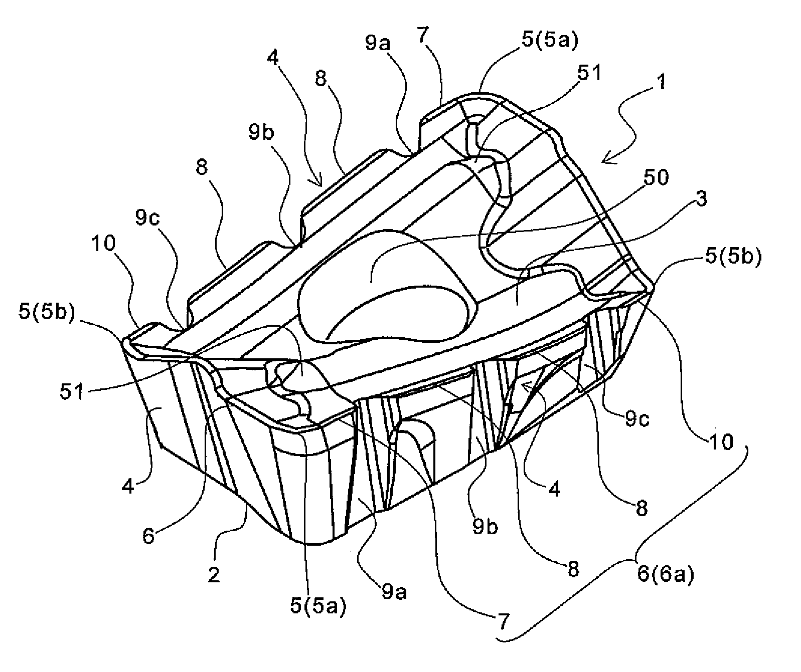
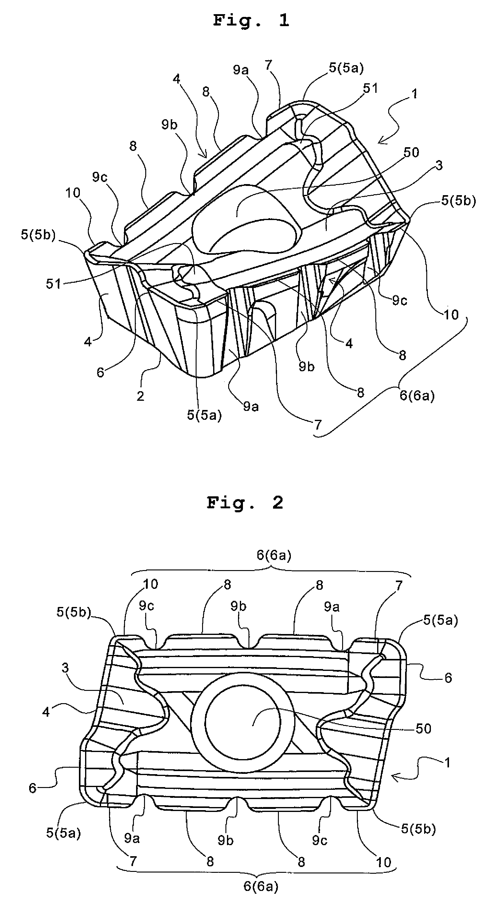
[0044]A first preferred embodiment of the cutting insert according to the invention is described in detail with reference to the accompanying drawings.

[0045]As shown in FIGS. 1 to 3, the cutting insert according to the first preferred embodiment (hereinafter referred to simply as an insert) 1 comprises an insert main body having substantially a parallelogram when viewed from above. The insert 1 comprises a bottom surface 2 serving as a seat surface, an upper surface 3 having a rake face, and a side surface 4 having a flank. The insert 1 comprises further corner portions 5 (5a and 5b) located at the corner parts of the insert main body in a ridge between the upper surface 3 and the side surface 4, and a cutting edge 6 located between these two corner portions 5 and 5 in the ridge (namely between both ends of the ridge) and connected to these two corner portions 5 and 5.

[0046]The rake face of the upper surface 3 means the face of the upper surface 3, through which generated chips graz...

second preferred embodiment

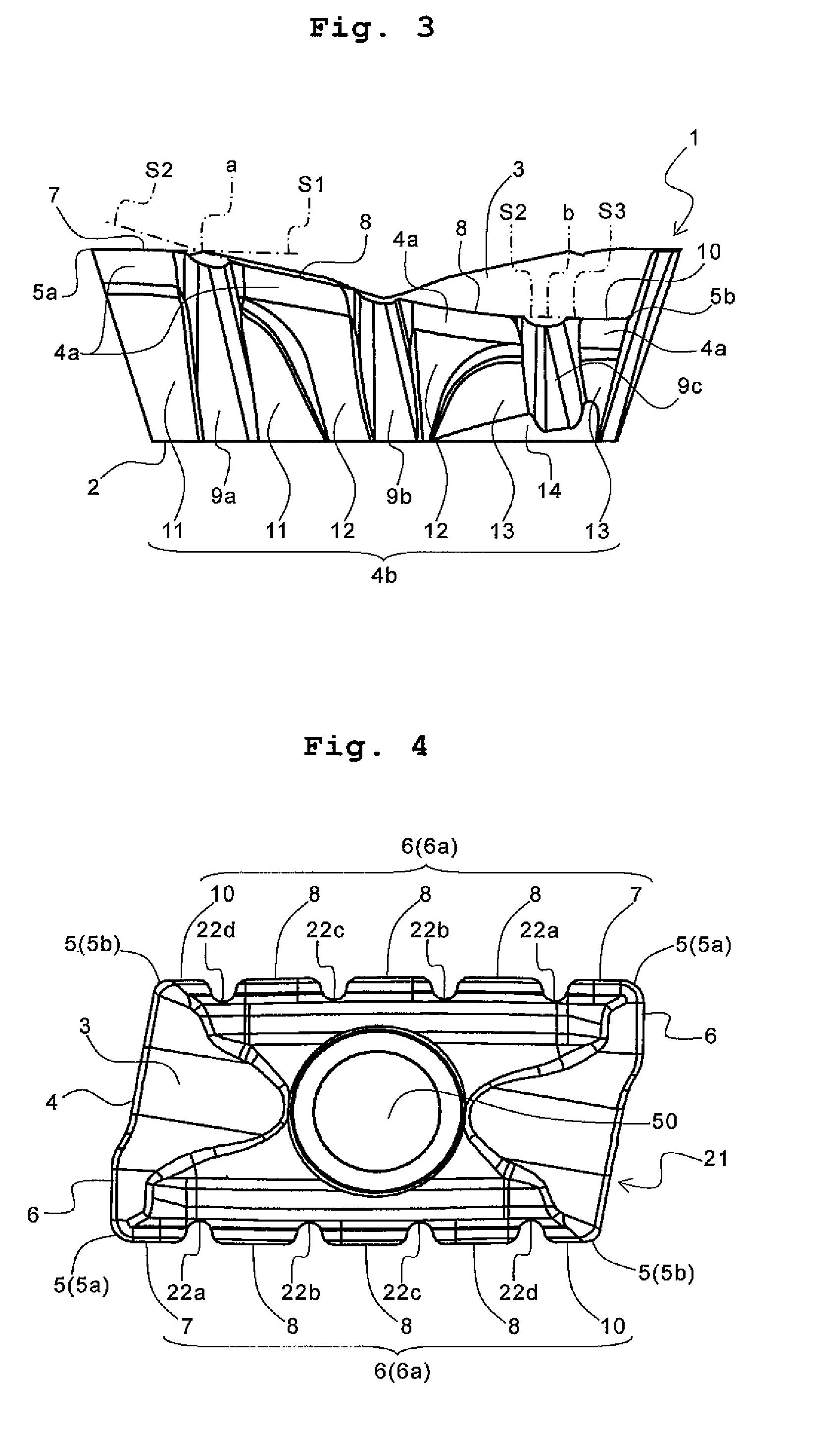
[0060]A second preferred embodiment next is described with reference to the accompanying drawings. In FIGS. 4 and 5 referred to here, the same references have been used as in FIGS. 1 to 3 for similar parts, and the description thereof is omitted.

[0061]The difference between the insert of the second preferred embodiment and the insert 1 of the first preferred embodiment is the number of grooves formed, that is, the former has four grooves and the latter has the three grooves. Specifically, as shown in FIGS. 4 and 5, an insert 21 of the second preferred embodiment comprises, on a side surface 4 in each longitudinal direction, grooves 22a, 22b, 22c and 22d as a plurality of grooves extending from the side surface 4 to an upper surface 3 to divide a main cutting edge 6a. Thus, the insert 21 has a larger number of the grooves than the insert 1, enabling a further reduction of the cutting force during cutting.

[0062]The groove 22a among these grooves 22a, 22b, 22c and 22d is formed at a re...

third preferred embodiment

[0066]A third preferred embodiment is next described with reference to the accompanying drawing. In FIG. 6 referred to here, the same references have been used as in FIGS. 1 to 5 for similar parts, and the description thereof is omitted.

[0067]The difference between the insert of the third preferred embodiment and the insert 21 of the second preferred embodiment is the formation of the first flank 11, the second flank 12 and the third flank 13 on the side surface extending from the cutting edge-side flank 4a to the bottom surface 2. That is, the former has none of these flanks, and the latter has all of them. Specifically, as shown in FIG. 6, in an insert 30 of the third preferred embodiment, a side surface 4c extending from a cutting edge-side flank 4a to a bottom surface 2 comprises a flank 15, whose clearance angle is gradually changed from a high-positioned corner cutting edge 5a toward a low-positioned corner portion 5b. This simplifies the process of machining the side surface ...


PUM

PropertyMeasurementUnit
thicknessaaaaaaaaaa
widthaaaaaaaaaa
heightaaaaaaaaaa

Abstract

An insert comprises an insert main body having an upper surface and a plurality of side surfaces, a cutting edge located between both ends of a ridge which is between at least one side surface among the side surfaces and the upper surface, a high-positioned portion located at one end of the ridge, and a low-positioned portion located lower in the thickness direction of the insert main body than the high-positioned portion and located at the other end of the ridge. The cutting edge comprises a first flat cutting edge having substantially the same height as the high-positioned portion, and a tilted cutting edge having a height decreasing from the high-positioned portion toward the low-positioned portion. On at least the one side surface, at least one groove extends from the side surface to the upper surface to divide the cutting edge by the groove, and at least the one groove is formed at a region including an intersection of a first extension line formed by imaginarily extending the first flat cutting edge with a second extension line formed by imaginarily extending the tilted cutting edge. This enables reduction in the occurrence of vibration during cutting, and the chipping.

Description

CROSS-REFERENCE TO THE RELATED APPLICATIONS[0001]This application is a national stage of international application No. PCT / JP2007 / 069109, filed on Sep. 28, 2007, which also claims the benefit of priority under 37 CFR 119 to Japanese Patent Application No. 2006-268838 filed on Sep. 29, 2006 and Japanese Patent Application No. 2006-268839 filed on Sep. 29, 2006, the entire contents of all of which are incorporated herein by reference.TECHNICAL FIELD[0002]The present invention relates to a cutting insert mounted on a cutting tool used for cutting of materials such as metal materials, a cutting tool using the cutting insert, and a cutting method.BACKGROUND ART[0003]Examples of the cutting tool generally used for cutting metal materials and the like include those that a cutting insert having a cutting edge is mounted thereon. For example, Patent Document 1 describes a predetermined cutting insert, and a cutting tool with the cutting insert mounted thereon (specifically, an end mill).[000...

Claims


Application Information

Patent Timeline
Patent Type & Authority Patents(United States)
IPC IPC(8): B23C5/20
CPCB23C5/109B23C5/202B23C2200/128B23C2200/205B23C2200/326Y10T407/1962Y10T408/909Y10T407/1924Y10T407/23Y10T409/303808Y10T408/03
Inventor HATTA, KAORU
Owner KYOCERA CORP
Why Eureka
Try Eureka