Cryo-ablation refrigerant distribution catheter

a technology of refrigerant distribution and cryoablation, which is applied in the field of cryoablation refrigerant distribution catheters, can solve the problems of reducing the heart's ability to properly function as a pump, affecting the quality of life, and affecting the ability to properly discharge fluid, so as to facilitate proper ablation procedures and reduce the risk of inconsistent cooling

Active Publication Date: 2013-11-12
BOSTON SCI SCIMED INC
View PDF22 Cites 25 Cited by
  • Summary
  • Abstract
  • Description
  • Claims
  • Application Information

AI Technical Summary

Benefits of technology

[0008]Described herein is a cryoablation catheter for use in tissue ablation. The catheter comprises an elongate supply lumen, or catheter body, which carries a cryofluid or refrigerant from a refrigerant supply unit. Generally, a source of refrigerant is connected to the proximal end of the supply lumen and the cryochamber, or expansion chamber, is located at the lumen's distal end. The ablation catheter also comprises a refrigerant dispersion member. The dispersion member, located near the distal end of the supply lumen, is at least partially housed by the expansion chamber and serves to evenly distribute the refrigerant exiting the distal end of the supply lumen across at least some portion of the interior of the expansion chamber. An even distribution of cryofluid can facilitate proper ablation procedures by reducing the risk of inconsistent cooling of the targeted tissue in contact with the ablation catheter tip.

Problems solved by technology

The rapid quivering reduces the heart's ability to properly function as a pump.
The disorder typically increases the risk of acquiring a number of potentially deadly complications, including thrombo-embolic stroke, dilated cardiomyopathy, and congestive heart failure.
Quality of life is also impaired by atrial fibrillation symptoms such as palpitations, chest pain, dyspnea, fatigue, and dizziness.
Surgical ablation has a much higher success rate than drug therapies and lacks the potential for side effects presented by drug treatment.
However, highly invasive (e.g., open-chest) procedures can present substantial risks.
However, in some instances, the refrigerant is not evenly distributed within the desired region of the expansion chamber.
This results in the non-uniform or uneven ablation of the targeted tissue.

Method used


Image

  • Cryo-ablation refrigerant distribution catheter
  • Cryo-ablation refrigerant distribution catheter
  • Cryo-ablation refrigerant distribution catheter

Examples


Embodiment Construction

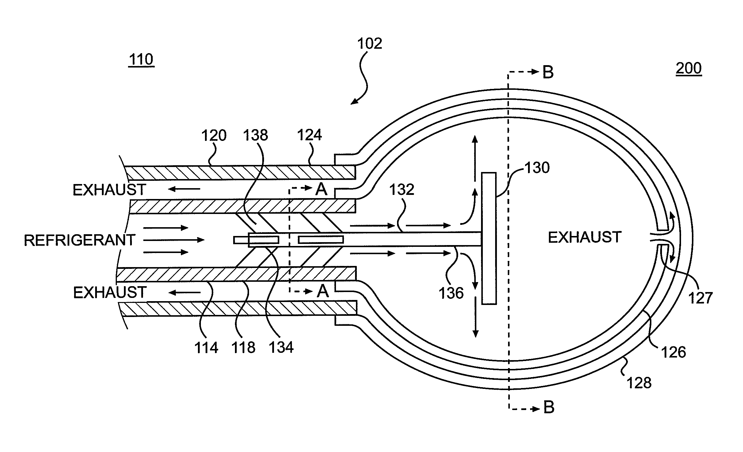
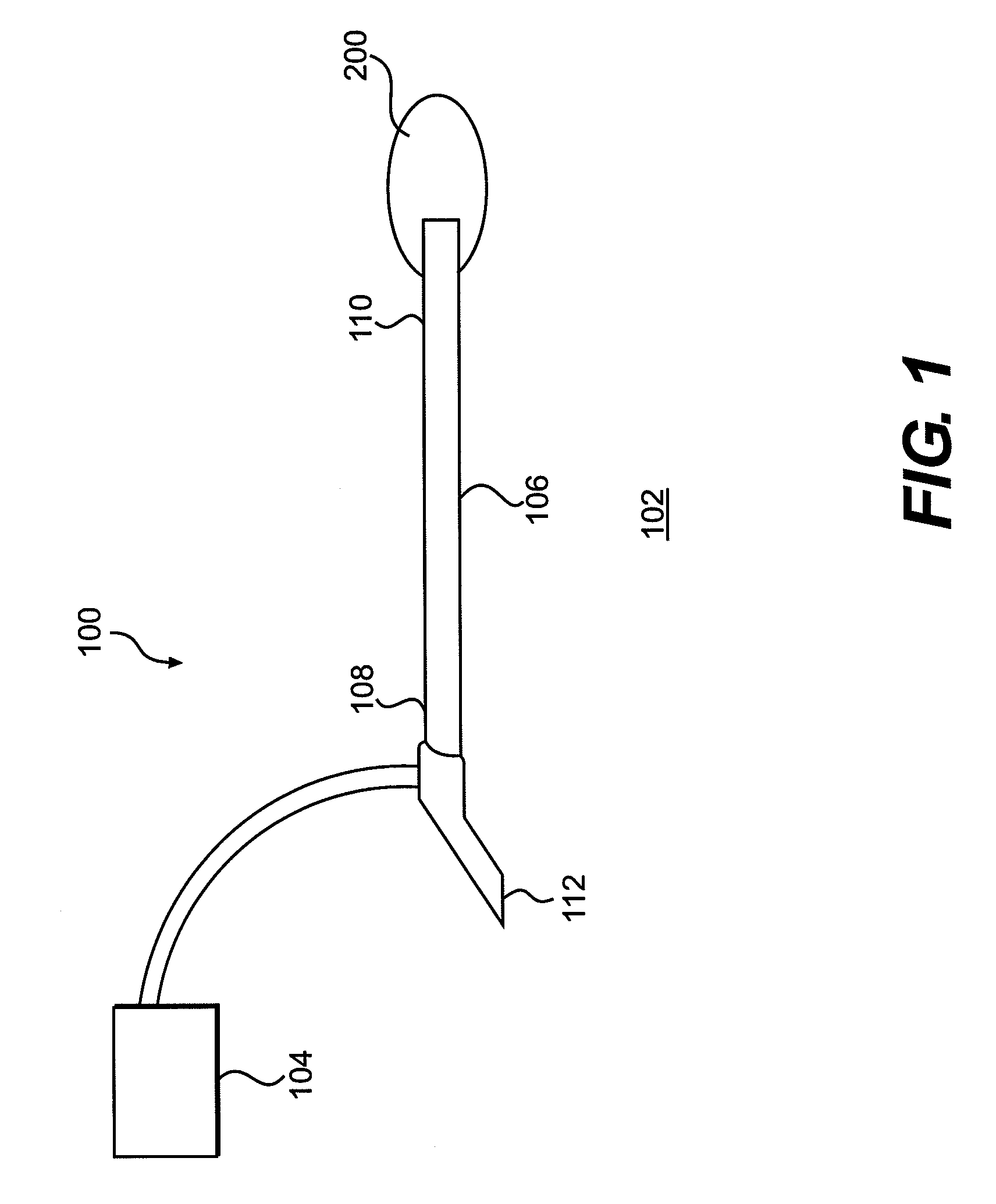
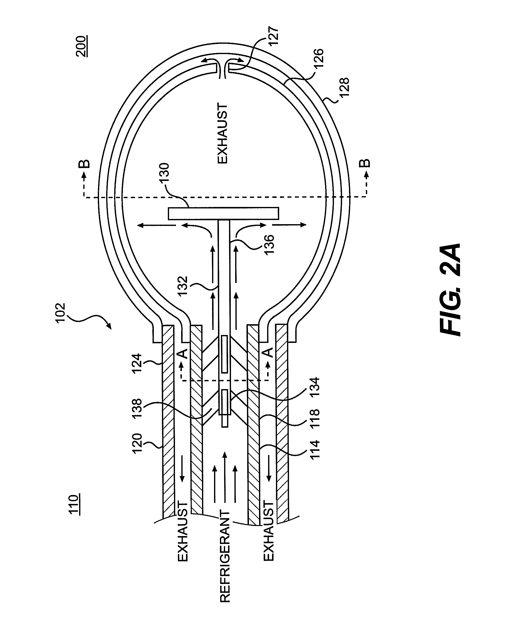
[0025]Disclosed herein are various embodiments of a cryoablation catheter device. Generally, the device allows an operator to cool tissue targeted for ablation in a consistent and / or uniform fashion. As part of various procedures, where ablation is to be performed in or around the pulmonary veins, it may be desirable to evenly cool the tissue in a circumferential band. Cryoablation catheters known in the art, in which refrigerant is simply released into the cryochamber, can result in an uneven distribution of cryofluid on a desired region of the interior wall of the cryochamber or uneven cooling of the targeted tissue. This, in turn, can necessitate additional ablations and extend procedure duration. The cyroablation catheter disclosed below solves this problem by positioning a dispersion member or dispersion body within the cyrochamber. In one aspect, the dispersion member serves to direct the cryofluid towards the interior wall of the expansion chamber in such a way as to ensure e...


PUM


Abstract

Described herein are methods and devices for performing ablation via a cryoablation catheter. An ablation catheter having a cyroablation chamber at its distal end can be used to achieve a uniform ablation band in or around the pulmonary veins. The cyrochamber can house a dispersion member in fluid communication with a refrigerant supply and can function to evenly distribute received refrigerant over some portion of the inner wall of the cryochamber. As a result of this even distribution of refrigerant within the cyrochamber, uniform ablation of the targeted tissue of the patient can be achieved.

Description

[0001]This application claims priority to Provisional Application Ser. No. 61 / 064,577 entitled “Cryo-Ablation Refrigerant Distribution Catheter” filed Mar. 13, 2008, which is incorporated herein by reference.BACKGROUND OF THE INVENTION[0002]Atrial fibrillation is the most common heart arrhythmia in the world, affecting over 2.5 million people in the United States alone. In fibrillation the upper chambers of the heart, known as the atria, quiver rapidly instead of beating in a steady rhythm. The rapid quivering reduces the heart's ability to properly function as a pump.[0003]The disorder typically increases the risk of acquiring a number of potentially deadly complications, including thrombo-embolic stroke, dilated cardiomyopathy, and congestive heart failure. Quality of life is also impaired by atrial fibrillation symptoms such as palpitations, chest pain, dyspnea, fatigue, and dizziness. People with atrial fibrillation have, on average, a five-fold increase in morbidity and a two-f...

Claims


Application Information

Patent Timeline
Patent Type & Authority Patents(United States)
IPC IPC(8): A61B18/18A61M37/00A61F2/958
CPCA61B18/02A61B2017/22051A61B2018/0022A61B2018/0212A61B2018/0262
Inventor HON, RAPHAEL
Owner BOSTON SCI SCIMED INC
Why Eureka
Try Eureka