
Methods and apparatus for performing valvuloplasty

a valvuloplasty and valve technology, applied in the field of valvuloplasty, can solve the problems of limiting the patient population on whom the procedure may be performed, limiting the amount of time, and limiting the number of patients

Active Publication Date: 2013-11-12
BOSTON SCI SCIMED INC
View PDF898 Cites 185 Cited by
  • Summary
  • Abstract
  • Description
  • Claims
  • Application Information

AI Technical Summary

Benefits of technology

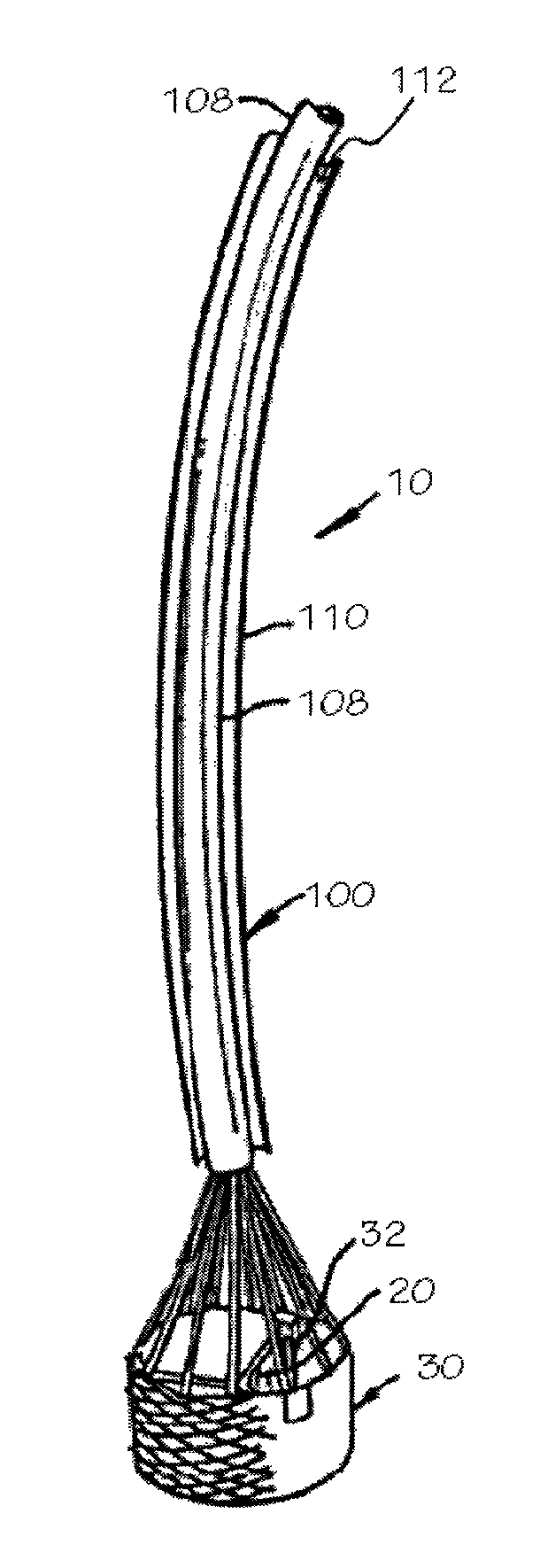
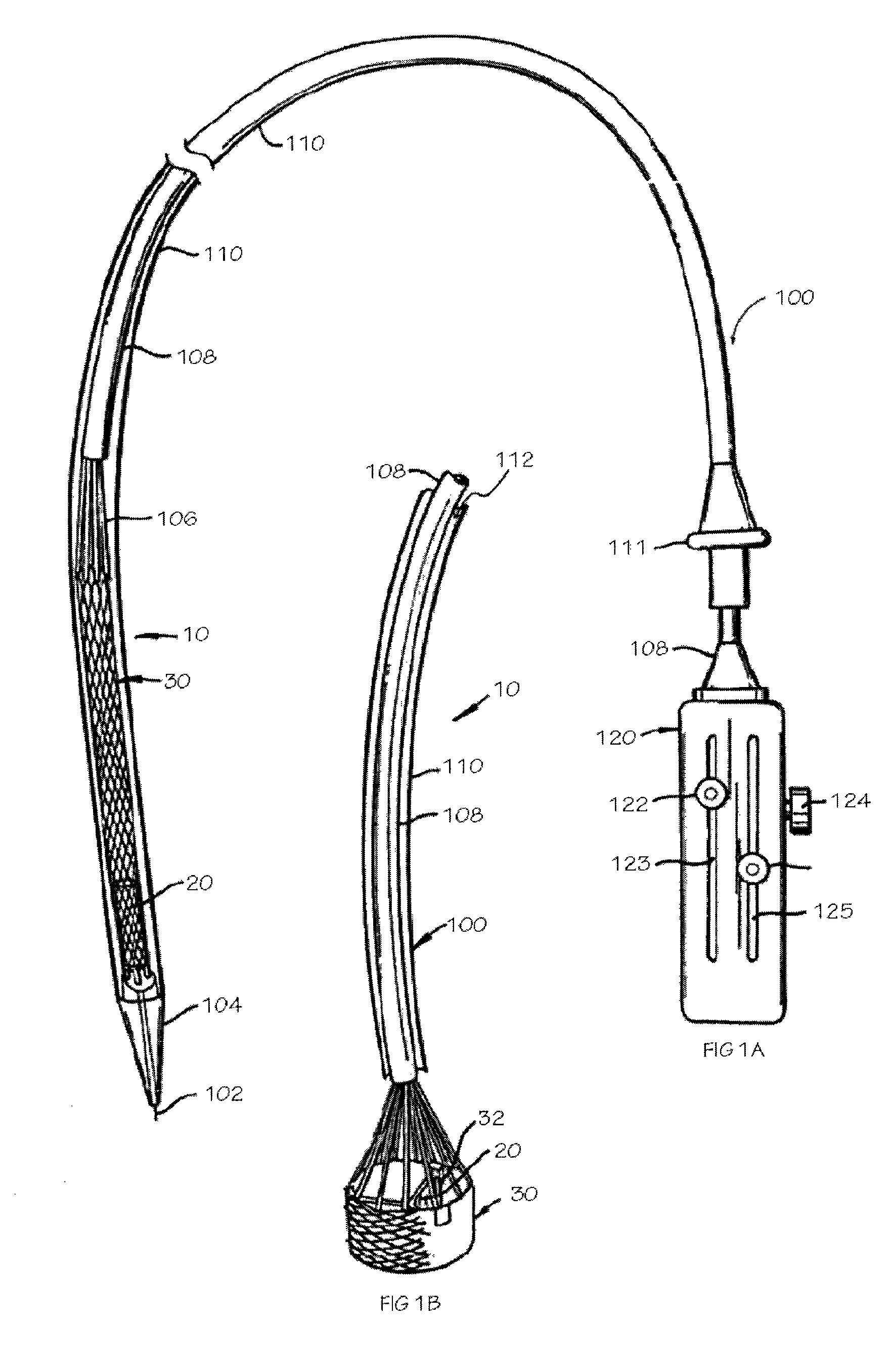
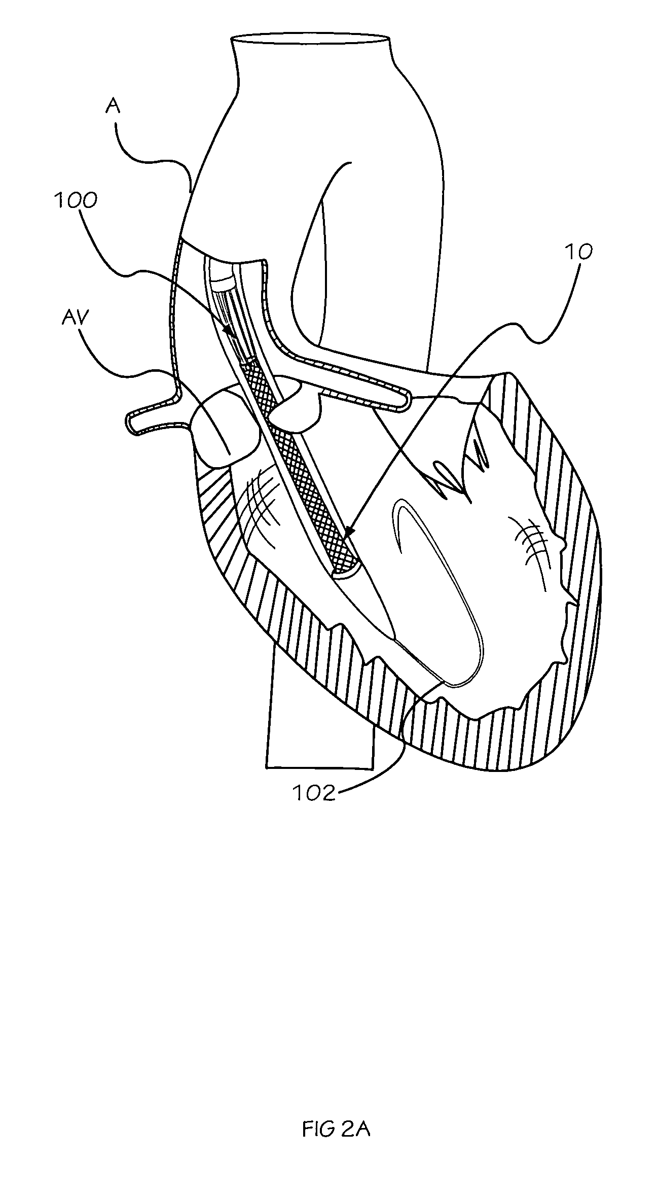
This patent describes an apparatus and method for performing valvuloplasty, which involves using an expandable braid valvuloplasty device and a delivery system for percutaneous delivery, expansion, and retrieval of the device at a valvuloplasty site to perform a valvuloplasty procedure. An optional valve can be used to regulate blood flow during the procedure. The method can also include monitoring the device during the procedure using measurement elements. Overall, this invention provides a minimally invasive method for repairing damaged heart valves.

Problems solved by technology

Failing heart valves can become calcified and stenotic.
Use of valvuloplasty in connection with PTVR is expected to present unique challenges not previously addressed or accounted for by the valvuloplasty prior art.
One problem associated with prior art balloon-based valvuloplasty devices is that the balloon may conform to the profile of the stenosed native valve, as opposed to forcing the stenosed valve to conform to a desired predetermined shape or profile of the balloon.
Furthermore, some balloon-based valvuloplasty devices completely occlude the native valve and thereby stop the flow of blood during the valvuloplasty procedure.
This severely limits the amount of time over which the procedure may be practiced and brings additional risks to the already debilitated patient, thereby limiting the patient population on whom the procedure may be performed.
As such, a balloon-based valvuloplasty device that incorporates a valve may only partially overcome the problem of flow occlusion during valvuloplasty, since its use may be limited by size constraints.
Another problem associated with prior art balloon-based valvuloplasty devices is the tendency of the valvuloplasty balloon to slip out of the stenotic area during the valvuloplasty procedure.
However, use of a valvuloplasty device incorporating a necked-in region requires precise placement of the valvuloplasty balloon prior to inflation and may not adequately dilate the target region.
These devices suffer from a number of shortcomings.
The minimal number of point contacts associated with the small number of ribs is expected to localize forces, thereby increasing the risk of localized tissue failure, e.g., perforation or dissection.
Such devices also may be less efficient at transmitting the force provided by the medical practitioner into the radially- and outwardly-directed forces necessary for expansion of the native stenosed valve, as compared to traditional balloon valvuloplasty devices.
Furthermore, these devices may require precise placement both axially and rotationally relative to the stenotic native valve.

Method used


Image

  • Methods and apparatus for performing valvuloplasty
  • Methods and apparatus for performing valvuloplasty
  • Methods and apparatus for performing valvuloplasty

Examples


Embodiment Construction

[0025]While preferred embodiments of the present invention are shown and described herein, it will be obvious to those skilled in the art that such embodiments are provided by way of example only. Numerous variations, changes and substitutions will now occur to those skilled in the art without departing from the invention. It should be understood that various alternatives to the embodiments of the invention described herein may be employed in practicing the invention. It is intended that the following claims define the scope of the invention and that methods and structures within the scope of these claims and their equivalents be covered thereby.

[0026]The present invention relates to methods and apparatus for performing valvuloplasty. More particularly, the present invention relates to methods and apparatus for performing valvuloplasty as an adjunct to percutaneous transcatheter heart valve replacement (“PTVR”). Such use in connection with PTVR is expected to present unique challeng...


PUM


Abstract

The present invention relates to apparatus and methods for performing valvuloplasty. In some embodiments, the apparatus includes an expandable braid valvuloplasty device. In some embodiments, the methods and apparatus may be used as an adjunct to percutaneous heart valve replacement. In some embodiments, the apparatus and methods may provide a medical practitioner with feedback, monitoring or measurement information, e.g., information relevant to percutaneous transcatheter heart valve replacement.

Description

CROSS-REFERENCE TO RELATED APPLICATIONS[0001]This application claims the benefit of priority of U.S. Provisional Application Ser. No. 60 / 724,455, filed Oct. 6, 2005, and is a continuation-in-part of application Ser. No. 10 / 982,692, filed Nov. 5, 2004, now U.S. Pat. No. 7,824,442, which is a continuation-in-part of application Ser. No. 10 / 746,120, now abandoned, filed 1; Dec. 23, 2003, which are incorporated herein by reference in their entirety and to which we claim priority under 35 USC §§119 and 120.INCORPORATION BY REFERENCE[0002]All publications and patent applications mentioned in this specification are herein incorporated by reference to the same extent as if each individual publication or patent application was specifically and individually indicated to be incorporated by reference.FIELD OF THE INVENTION[0003]The present invention relates to methods and apparatus for performing valvuloplasty. More particularly, the present invention relates to methods and apparatus for perfor...

Claims


Application Information

Patent Timeline
Patent Type & Authority Patents(United States)
IPC IPC(8): A61F2/24
CPCA61F2/2418A61F2/2439A61F2/90A61F2/2412A61B2017/00783A61F2002/9517A61F2250/0097A61F2/9517
Inventor SALAHIEH, AMRMOREJOHN, DWIGHT P.HILDEBRAND, DANIELSAUL, TOM
Owner BOSTON SCI SCIMED INC
Learn More