Blood treatment apparatus
a blood treatment apparatus and blood technology, applied in the direction of filtration separation, multi-stage water/sewage treatment, separation process, etc., can solve the problems of complex design of the apparatus, inability to achieve the desired level of ultrafiltration, and failure to provide an overall optimal fluid flow in the blood treatment apparatus
- Summary
- Abstract
- Description
- Claims
- Application Information
AI Technical Summary
Benefits of technology
Problems solved by technology
Method used
Image
Examples
first embodiment
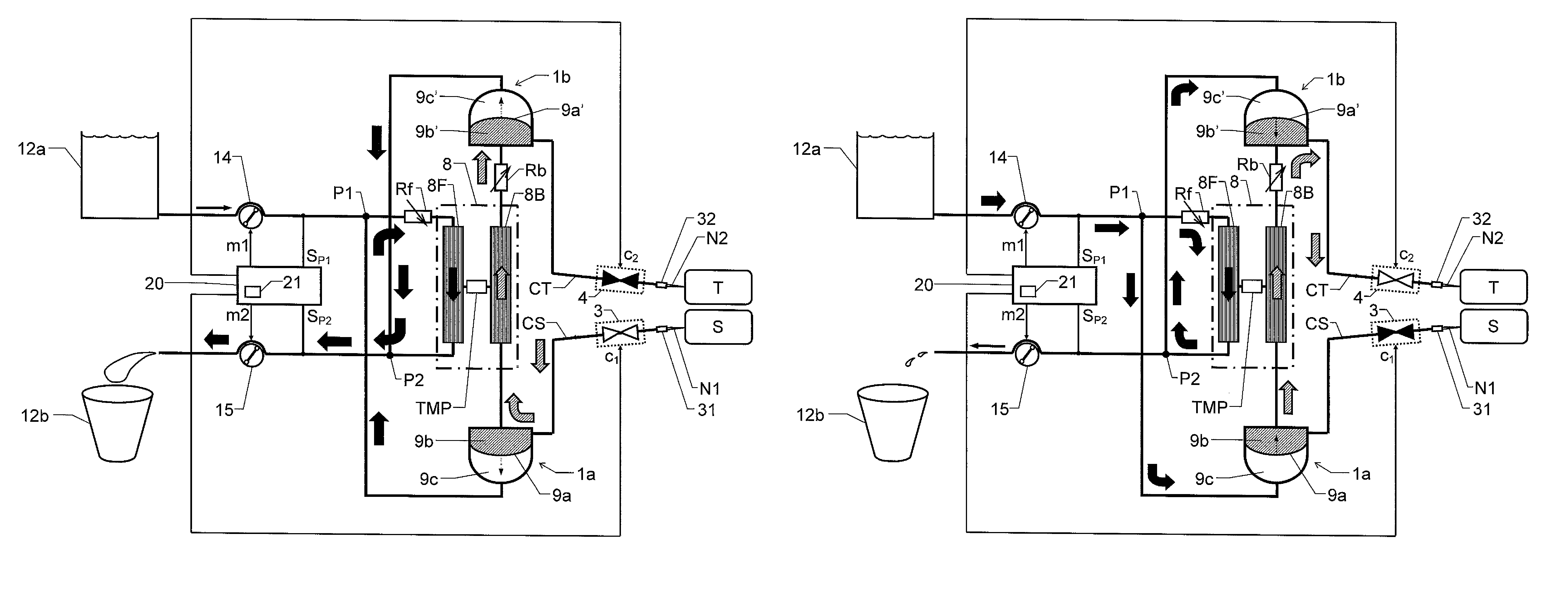
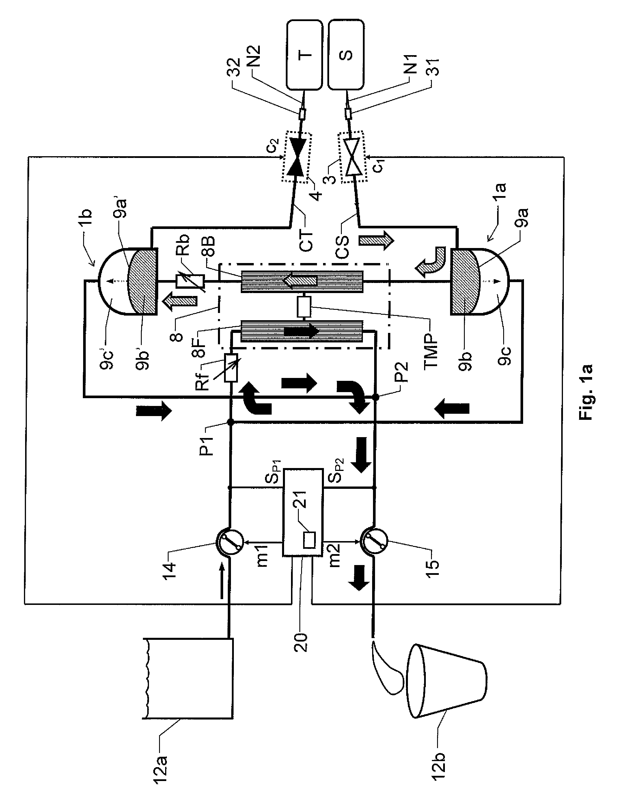
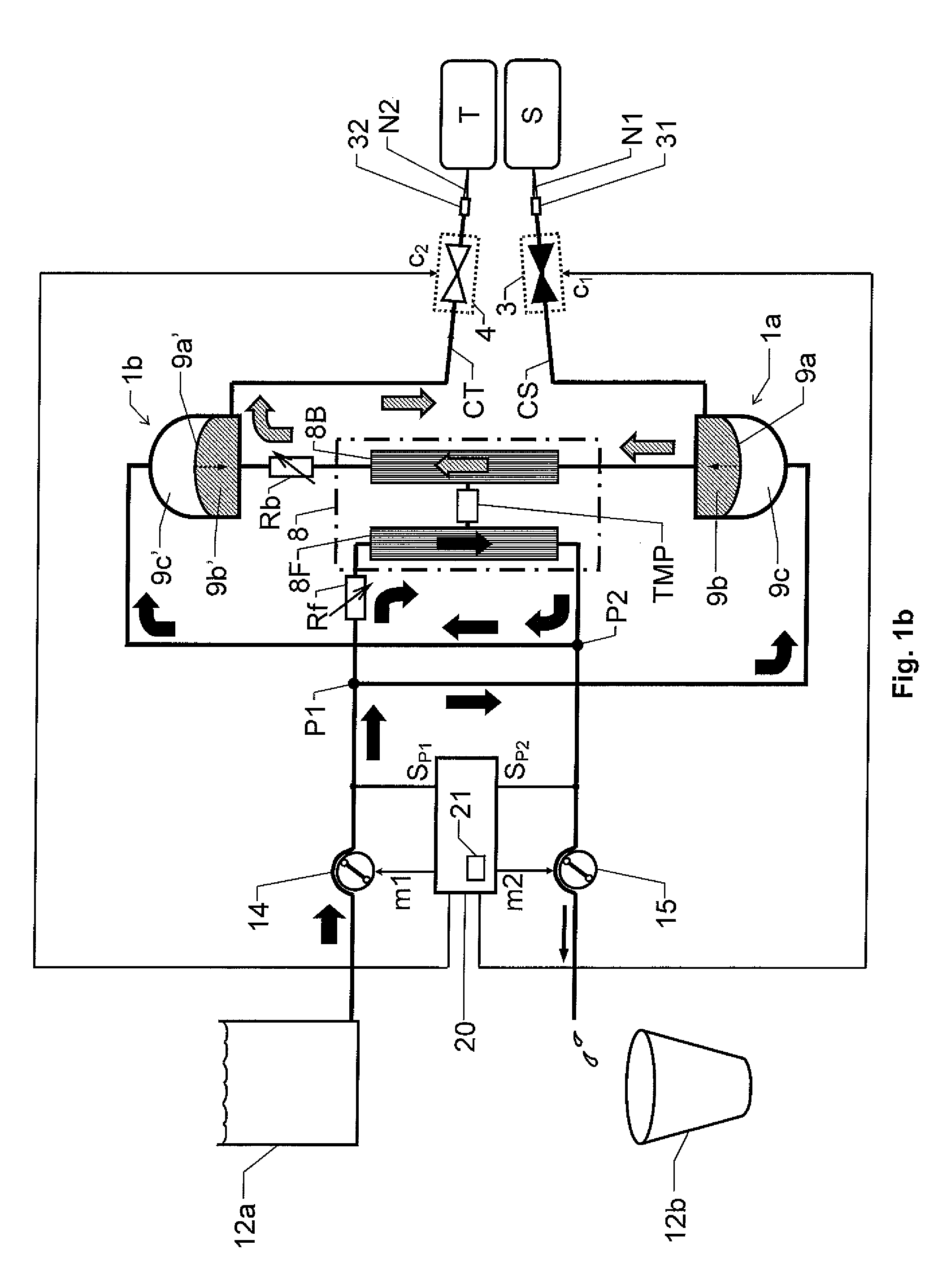
[0038]We refer initially to FIG. 1a, which shows a block diagram over a blood treatment apparatus (e.g. a dialysis apparatus) according to the invention during a first phase of a proposed cyclic blood treatment process.
[0039]The apparatus includes a blood treatment unit 8 (typically represented by a dialyzer), first and second fluid pumps 14 and 15 respectively and first and second blood pumps 1a and 1b respectively. First and second blood valve means 3 and 4 respectively are also included, which are controlled to be open and closed in an alternating fashion, such that the first blood valve means 3 is open when the second blood valve means 4 is closed, and vice versa.
[0040]The blood treatment unit 8 has a blood side 8B and a fluid side 8F that are separated by means of a semi-permeable membrane structure. For example, this structure may be represented by a large number of hollow fibers whose walls constitute a respective semi-permeable membrane and which fibers are configured to tra...
second embodiment
[0061]FIGS. 3a and 3b show block diagrams over a blood treatment apparatus according to the invention during a first and a second phase respectively of the proposed cyclic treatment process. In FIGS. 3a and 3b all units and components having reference signs, which also occur in FIGS. 1a and 1b designate the same units and components as those described above with reference to FIGS. 1a and 1b.
[0062]The second embodiment differs from the first embodiment of the invention in that the fluid pumps 14 and 15 are included in the respective fluid paths which connect the blood pumps 1a and 1b to the blood treatment unit 8. In the second embodiment, the first fluid pump 14 is arranged in a conduit between the second blood pump 1b and an inlet configured to receive fresh blood treatment fluid into the blood treatment unit 8. Analogously, the second fluid pump 15 is arranged in a conduit between the first blood pump 1a and an outlet configured to emit used blood treatment fluid from blood treat...
third embodiment
[0066]FIGS. 4a and 4b show block diagrams over a blood treatment apparatus according to the invention during a first and a second phase respectively of the proposed cyclic treatment process. In FIGS. 4a and 4b all units and components having reference signs, which also occur in FIGS. 1a, 1b, 3a and 3b designate the same units and components as those described above with reference to FIGS. 1a, 1b, 3a and 3b.
[0067]The third embodiment differs from the second embodiment of the invention in that the flow control means instead of one or more auxiliary fluid pumps, includes first and second adjustable flow restrictors Rf1 and Rf2 respectively. The first adjustable flow restrictor Rf1 is controllable in response to a first restriction control signal r1 from the control unit 20, and the second adjustable flow restrictor Rf2 is controllable in response to a second restriction control signal r2 from the control unit 20.
[0068]The first adjustable flow restrictor Rf1 is arranged in a first blo...
PUM
| Property | Measurement | Unit |
|---|---|---|
| volume | aaaaa | aaaaa |
| volume | aaaaa | aaaaa |
| fluid pressure drop | aaaaa | aaaaa |
Abstract
Description
Claims
Application Information
 - R&D
- Intellectual Property
- Life Sciences
- Materials
- Tech Scout
- Unparalleled Data Quality
- Higher Quality Content
- 60% Fewer Hallucinations
Browse by: Latest US Patents, China's latest patents, Technical Efficacy Thesaurus, Application Domain, Technology Topic, Popular Technical Reports.
© 2025 PatSnap. All rights reserved.Legal|Privacy policy|Modern Slavery Act Transparency Statement|Sitemap|About US| Contact US: help@patsnap.com


