Blood treatment apparatus
a treatment apparatus and blood technology, applied in the field of extracorporeal blood treatment, can solve the problems of inability to provide an overall optimal fluid flow in the blood treatment apparatus, compulsion to be relatively complex in the design of the apparatus, and inability to achieve the effect of facilitating the flow of fluid through the treatment apparatus
- Summary
- Abstract
- Description
- Claims
- Application Information
AI Technical Summary
Benefits of technology
Problems solved by technology
Method used
Image
Examples
first embodiment
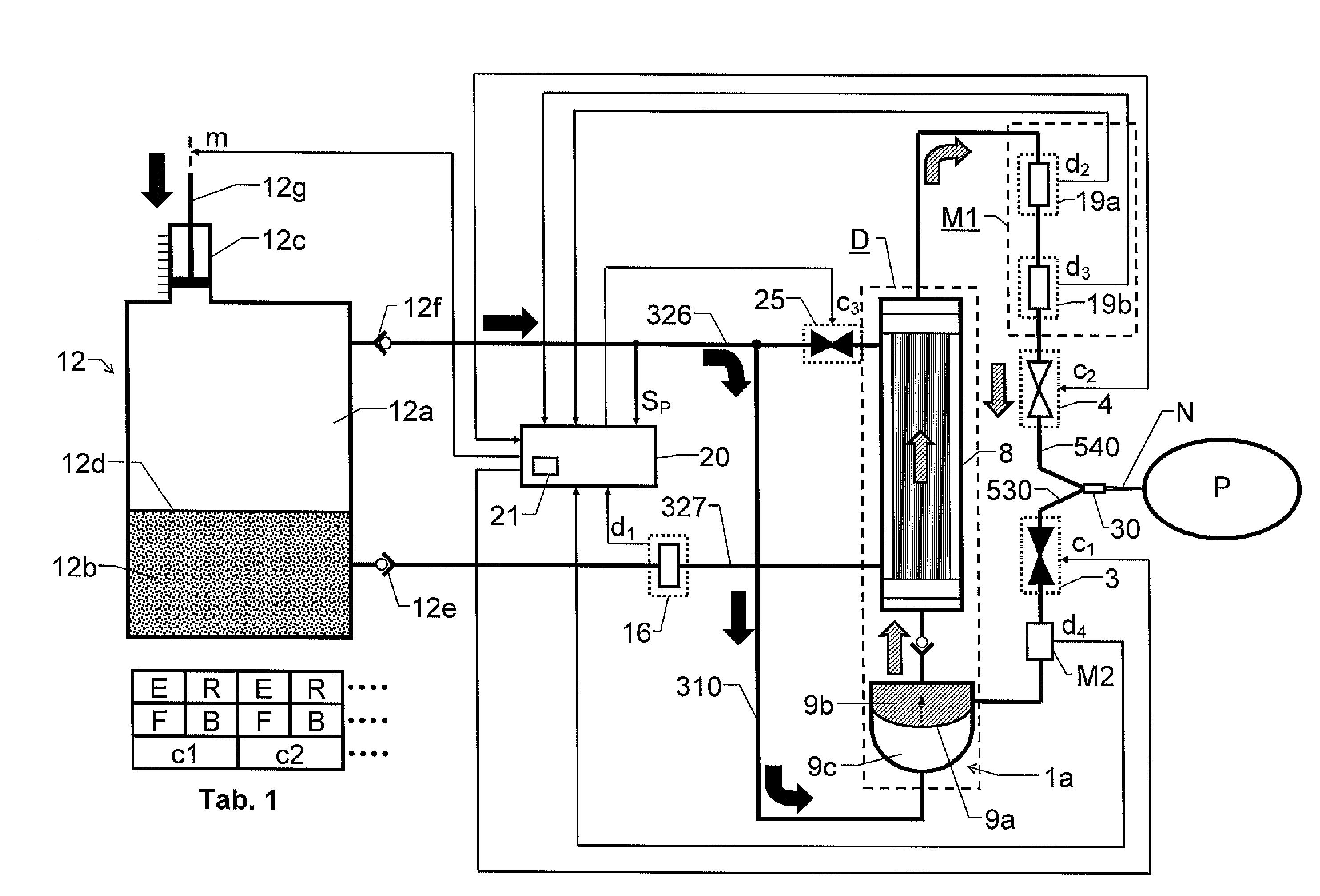
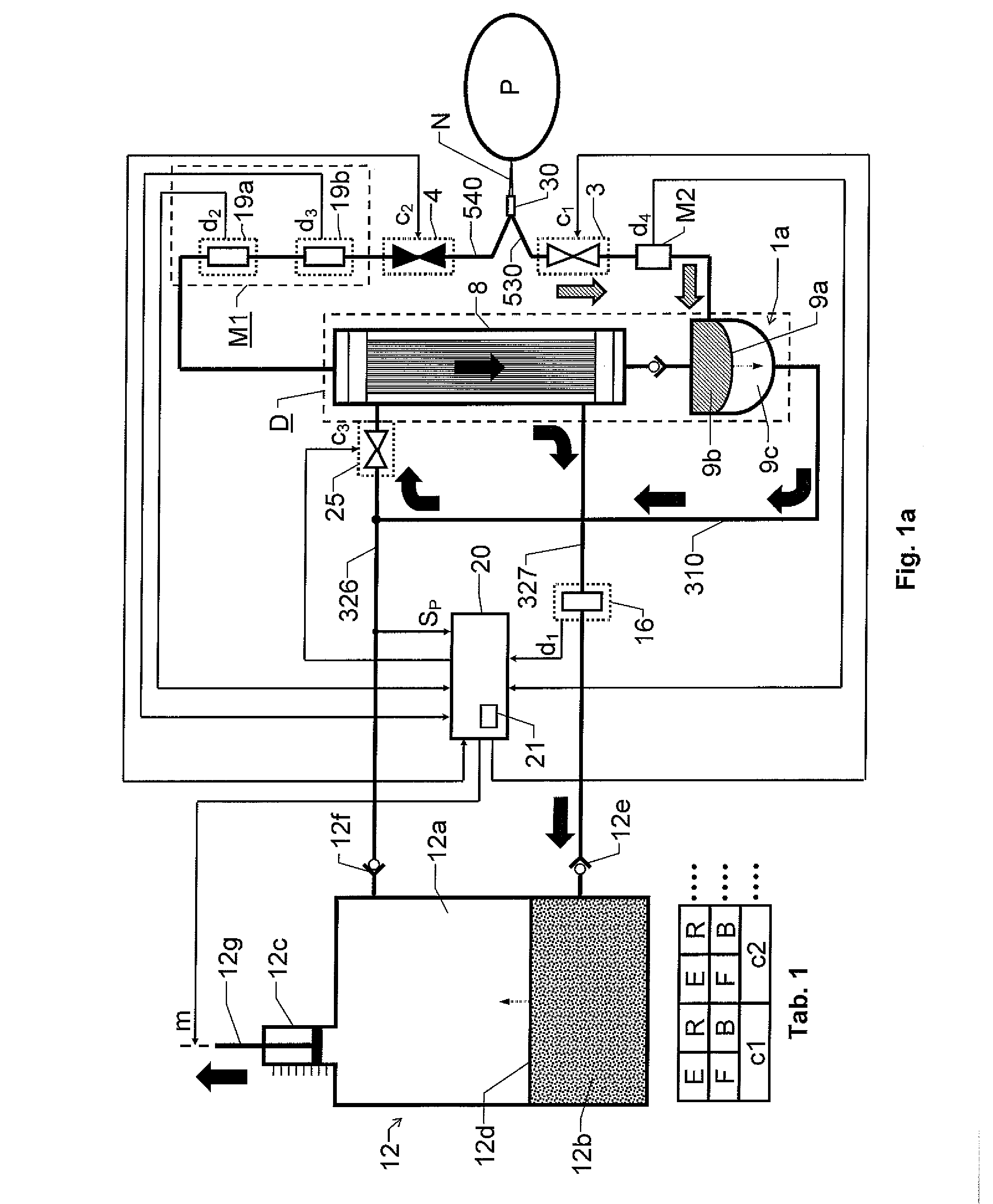
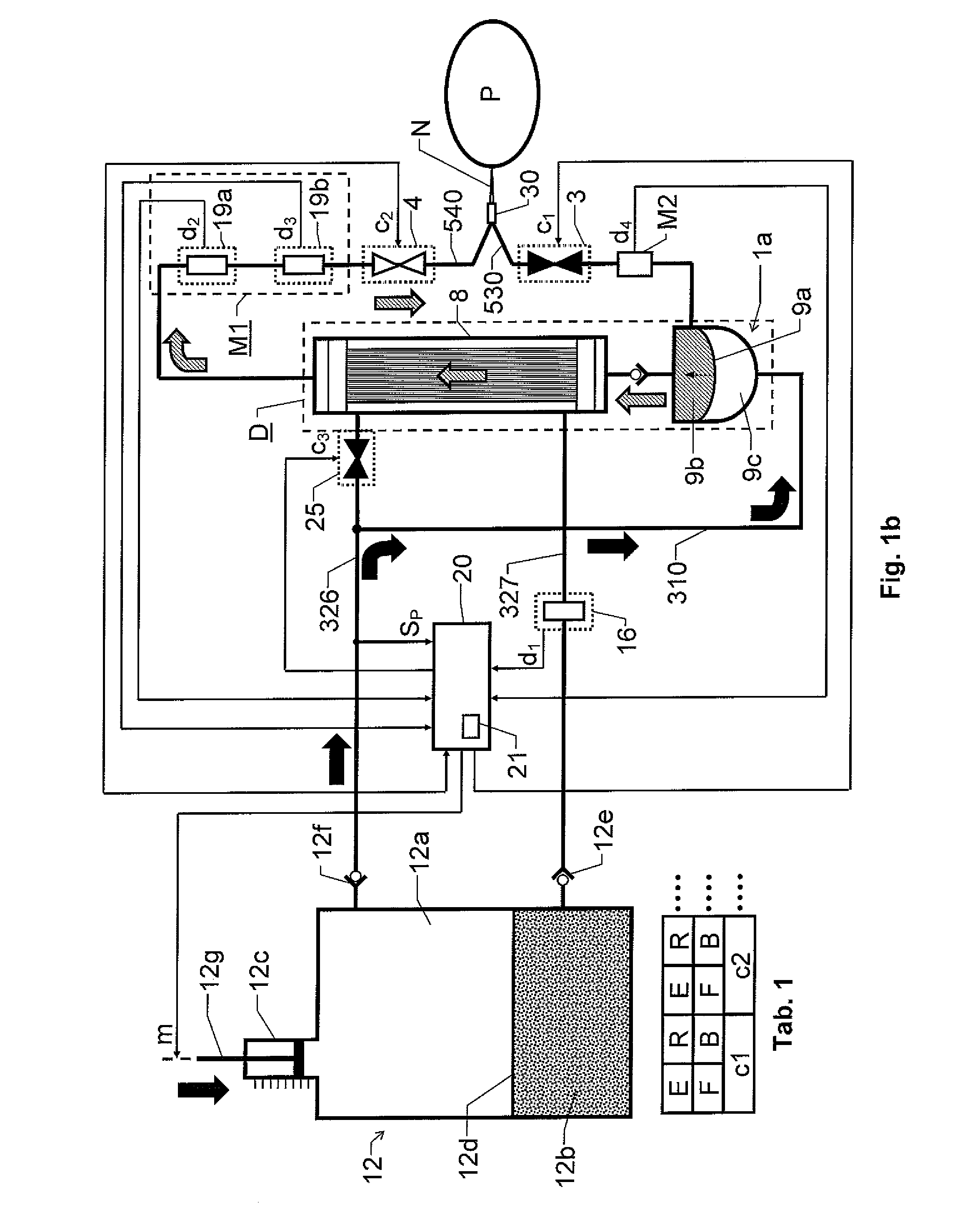
[0031]We refer initially to FIG. 1a, which shows a block diagram over a blood treatment apparatus (e.g. a dialysis apparatus) according to the invention during a first phase of a cyclic process.
[0032]The apparatus includes a blood treatment unit 8 (typically represented by a dialyzer), a reciprocal fluid pump 12c and a blood pump 1a. The fluid pump 12c is configured to pass a blood treatment fluid (e.g. dialysis fluid) from a reservoir compartment 12a of a rigid fluid container 12 through the blood treatment unit 8, however via the blood pump 1a. The blood pump 1a is further configured to extract untreated blood from a blood source, here represented by a patient P; pass the extracted blood through the blood treatment unit 8 and deliver treated blood to a target vessel, here again represented by the patient P. According to the invention, the fluid pump 12c is configured to control the operation of the blood pump 1a via the blood treatment fluid. Moreover, the blood pump 1a is integra...
second embodiment
[0052]FIG. 2a shows a block diagram over a blood treatment apparatus according to the invention during a first phase of a cyclic treatment process. All units and components having reference signs which also occur in FIGS. 1a and 1b designate the same units and components as those described above with reference to FIGS. 1a and 1b. To underline that fact that, according to the invention, the process of blood extraction and blood delivery need not involve a patient, FIGS. 2a and 2b illustrate a general blood source S and a general target vessel T. For example, a respective blood bag may represent the blood source S and the target vessel T. Of course, alternatively, both of these entities S and T may be represented by a patient. Consequently, it includes two needles N1 and N2 connected to the blood circuit via a respective needle connector 31 and 32.
[0053]In FIGS. 2a and 2b, the apparatus includes two blood pumps 1a and 1b respectively. Such a double-pump design is advantageous because ...
fourth embodiment
[0078]FIG. 7 shows a perspective view of the proposed joint apparatus element according to the invention. Here, all units, components and ports having reference signs, which also occur in FIG. 6f designate the same units and components as those described above with reference to FIG. 6f. In contrast to FIG. 6f, FIG. 7 depicts four ports 326, 326′, 327 and 327′ respectively configured to handle blood treatment fluid.
[0079]Such a design is required in order to enable the fluid pumps 14 and 15 to be included in the fluid paths between the blood pumps 1a and 1b and the blood treatment unit 8, and thereby not necessarily disposable.
[0080]FIG. 9a shows a block diagram over an apparatus similar to the one shown in FIG. 8, however in this apparatus the second accumulation container 9c′ of the second blood pump 1b is provided with an inlet for working fluid that is separate from an outlet for the working fluid. The features in FIG. 9a have reference signs that correspond to those used in conn...
PUM
 Abstract
Description
Claims
Application Information
 - R&D
- Intellectual Property
- Life Sciences
- Materials
- Tech Scout
- Unparalleled Data Quality
- Higher Quality Content
- 60% Fewer Hallucinations
Browse by: Latest US Patents, China's latest patents, Technical Efficacy Thesaurus, Application Domain, Technology Topic, Popular Technical Reports.
© 2025 PatSnap. All rights reserved.Legal|Privacy policy|Modern Slavery Act Transparency Statement|Sitemap|About US| Contact US: help@patsnap.com


