
Multiple-input multiple-output (MIMO) antenna system

a multi-input, multi-output technology, applied in the direction of independent non-interaction antenna combinations, substation equipment, transmission, etc., can solve the problems of affecting the symmetries of near-field coupling with the user's body, placing significant constraints on the handset id, architecture and mechanics, and difficult to achieve proper antenna isolation

Active Publication Date: 2013-11-19
MOTOROLA SOLUTIONS INC
View PDF19 Cites 15 Cited by
  • Summary
  • Abstract
  • Description
  • Claims
  • Application Information

AI Technical Summary

Benefits of technology

The present patent is about a method and apparatus for improving the implementation of MIMO antenna systems in wireless communication devices. The technical effects of the patent include optimizing efficiency and pattern correlation in MIMO antenna systems, which can be difficult and constrain the architecture of the device. The patent proposes a method of determining feeding profiles based on the eigenvectors of a suitable mathematical representation of the antenna system, which enhances system performance in terms of range and capacity, and improves user experience and reliability. The method and apparatus allow for greater flexibility and adaptability in MIMO antenna systems, particularly in portable devices.

Problems solved by technology

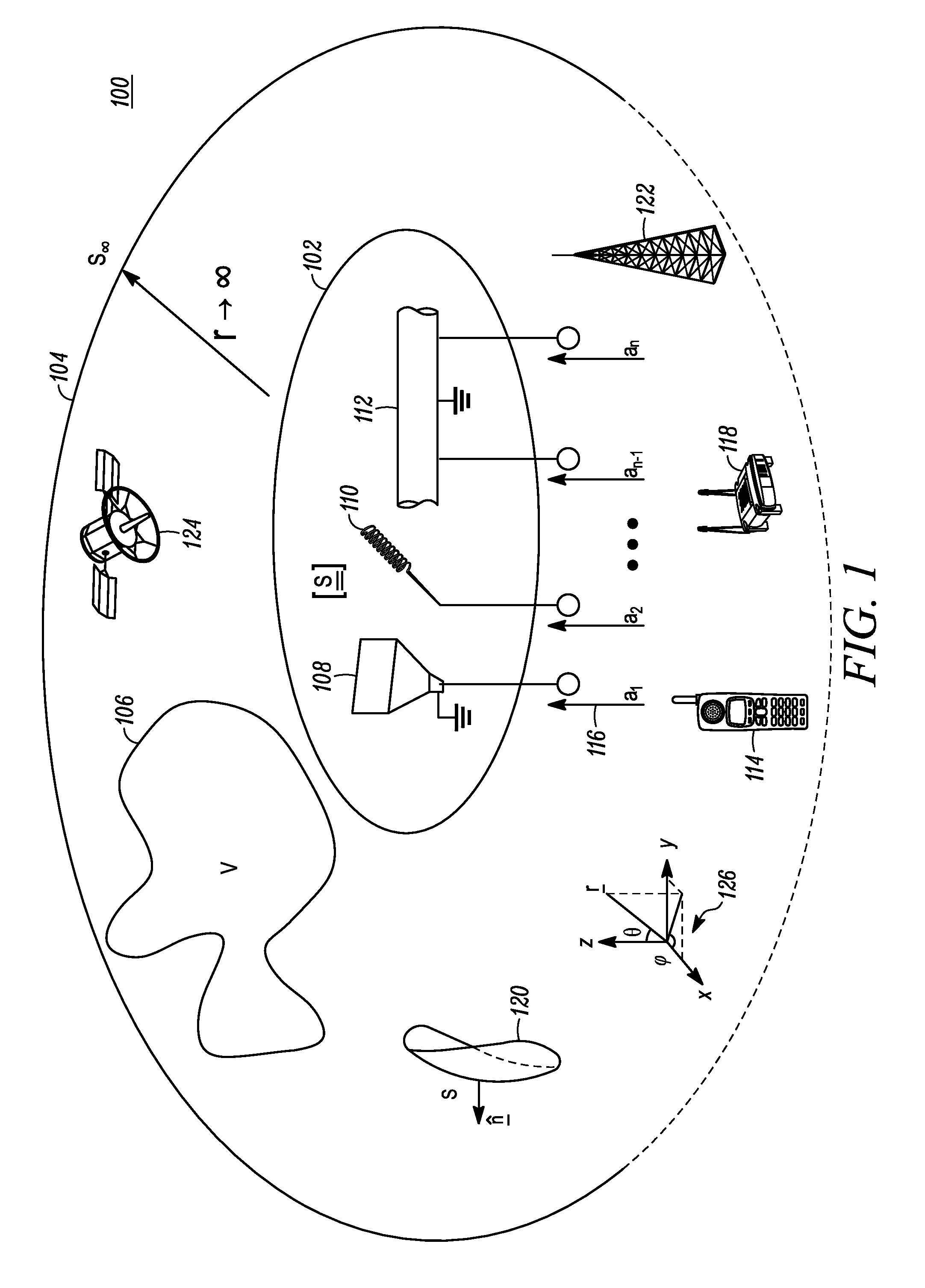
Presently, multi-port antenna systems for MIMO are designed by decoupling the antenna ports electrically, which is difficult and poses many geometrical and mechanical constraints, particularly in crowded and electrically small handsets.
However, all of these decoupling approaches place significant constraints on the handset ID, architecture, and mechanics.
Furthermore, near-field coupling with the user's body disrupts symmetries.
Additionally, implementing MIMO antenna systems under volume constraints makes it difficult to achieve proper antenna isolation.
Portable radios do not typically allow placing antenna elements at large electrical distances from each other, or to readily achieve polarization orthogonality, thus making much more challenging to achieve uncorrelated patterns and reducing the processing gain (and data throughput) achievable by simply feeding different uncorrelated signals to distinct antenna elements.
However, the use of different incident-wave eigenvector excitations, defined according to one of the aforementioned representations, to carry distinct uncorrelated signals allows achieving uncorrelated patterns even when the radiating structure features significant correlation between the fields excited from each port separately.
This can represent a challenge in portable wireless applications since having multiple high-power amplifiers increases battery current drain, product cost, heat dissipation requirements, and the required volume.
Multiple uncorrelated antenna patterns can be difficult to realize in a portable communication devices of a physical size comparable to the wavelength.
This approach, however, requires the use of two high-power RF amplifiers which, as previously discussed, may result in significant challenges for portable wireless communication devices.
There are cases where estimating the phase of the scattering parameters could be too onerous, from a cost, complexity, computational burden, and overall RF performance viewpoint.
For instance, severe antenna detuning could in some cases alter substantially the net input power at select antenna ports, which in turn may distort significantly the desired field distributions corresponding to predetermined reference states.

Method used


Image

  • Multiple-input multiple-output (MIMO) antenna system
  • Multiple-input multiple-output (MIMO) antenna system
  • Multiple-input multiple-output (MIMO) antenna system

Examples


Embodiment Construction

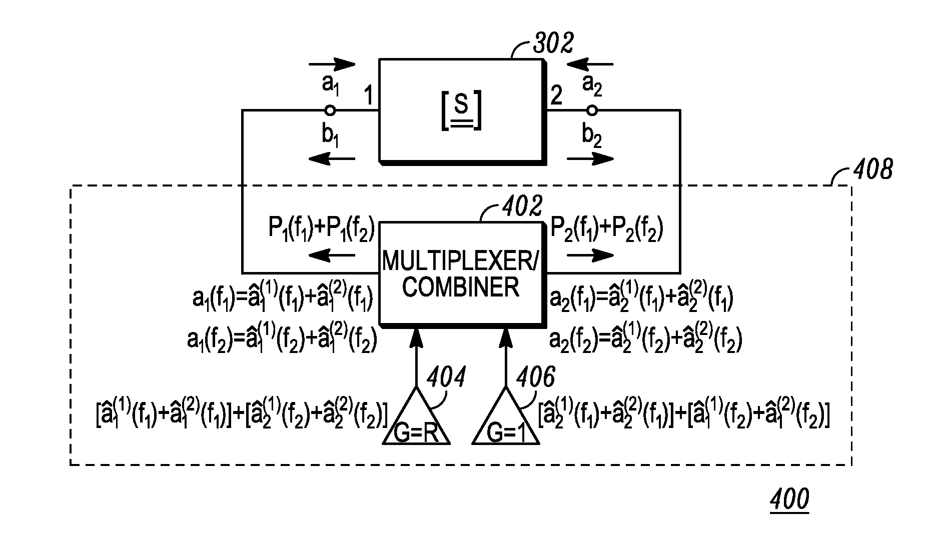
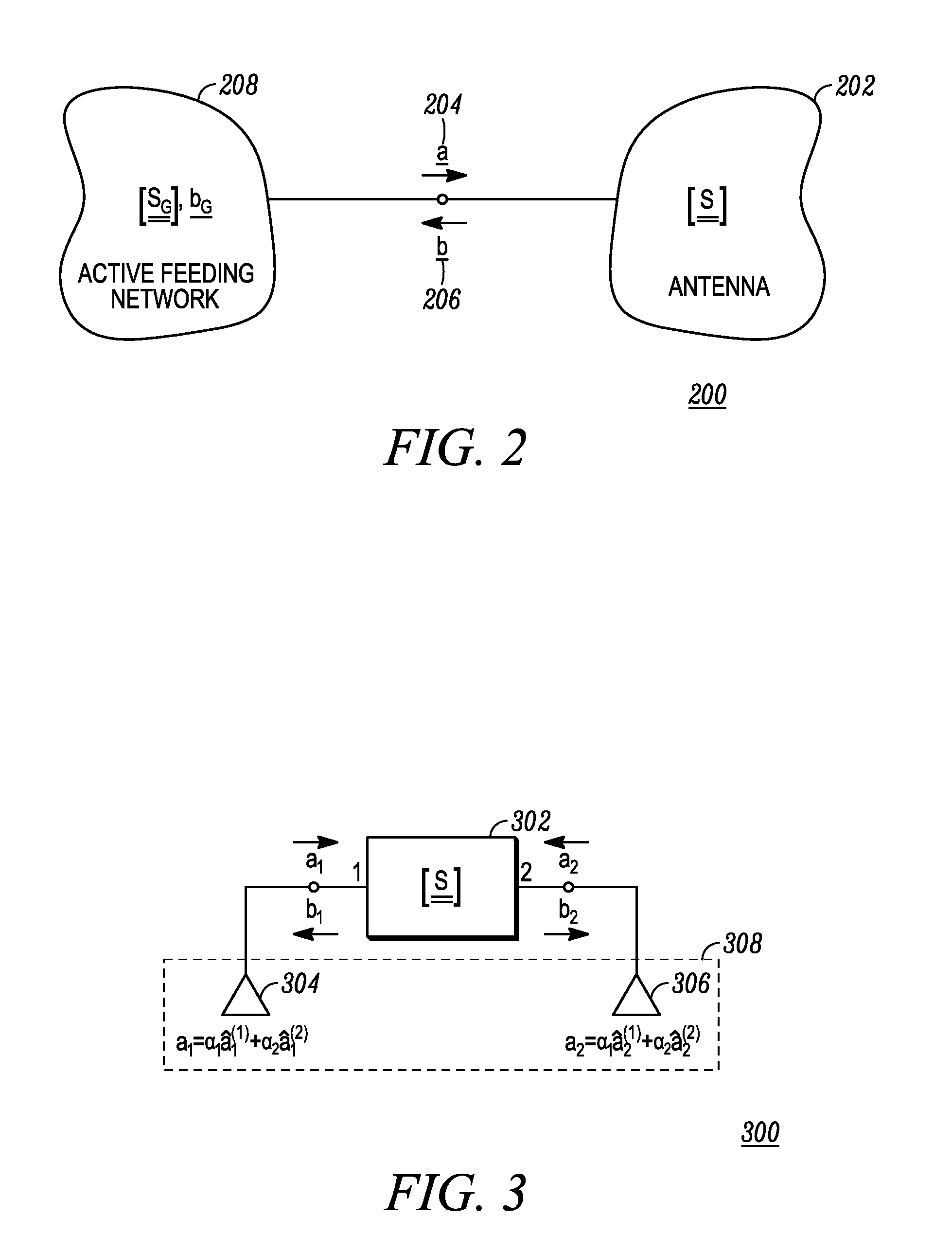
[0018]Briefly, in accordance with various embodiments to be described herein, there is provided a multiple-input multiple-output (MIMO) antenna system realized by defining feeding profiles based on the eigenvectors of a suitable mathematical representation of the antenna system. The MIMO antenna system formed and operating in accordance with the various embodiments enhances system performance in terms of range and capacity (i.e. efficiency and data throughput), which in turn enhances system reliability and user experience.

[0019]In accordance with the various embodiments, a suitable matrix representation of the MIMO antenna system is employed to determine eigenvectors associated with the multiple antenna feeds. These “eigen-feed” configurations have the property of exciting uncorrelated “antenna modes” that have distinct efficiencies. The modes are uncorrelated regardless of the actual antenna elements geometries and their mutual coupling. By suitable transformation of the “eigen-fee...


PUM


Abstract

An antenna system includes a multi-port antenna with an active feeding network coupled thereto. The active feeding network applies complex weights to signals received from and transmitted to each port of the multi-port antenna. The complex weights are applied according to eigenvectors corresponding to a Hermitian matrix representation of the multi-port antenna. The Hermitian matrix may be based on such multi-port antenna parameters such as power dissipation, power radiation, real-power flow, volumetric storage of electromagnetic energy, and / or volumetric dissipation of electromagnetic energy. The multi-port antenna yields orthogonal electromagnetic fields in volumes or surfaces of interest in response to the active feeding network excitation.

Description

FIELD OF THE DISCLOSURE[0001]The present disclosure relates generally to multiple-input multiple-output (MIMO) antenna systems and more particularly to a method and apparatus for optimizing efficiency and pattern correlation in MIMO antenna systems in fixed and portable communication devices.BACKGROUND[0002]Multiple-input multiple-output (MIMO) radio communication techniques increase the throughput of a communication system by taking advantage of multiple transmit and multiple receive antennas, which can be generally considered belonging to the class of multi-port antennas. MIMO methods use multi-port antennas having radiation patterns featuring low correlation. Low correlation may be a result of low electrical coupling between antenna ports. Presently, multi-port antenna systems for MIMO are designed by decoupling the antenna ports electrically, which is difficult and poses many geometrical and mechanical constraints, particularly in crowded and electrically small handsets. Antenna...

Claims


Application Information

Patent Timeline
Patent Type & Authority Patents(United States)
IPC IPC(8): H01Q1/50
CPCH01Q1/521H01Q21/28H04B7/0413
Inventor FARAONE, ANTONIODINALLO, CARLOCICCHETTI, RENATO
Owner MOTOROLA SOLUTIONS INC
Learn More