
Display apparatus and control method thereof

a control method and display device technology, applied in the field of display devices and control methods thereof, can solve the problems of increasing difficulty in ensuring the space of the control panel provided with the plurality of buttons, difficult control panel design, and inconvenient user pressing a small button

Active Publication Date: 2013-11-19
SAMSUNG ELECTRONICS CO LTD
View PDF4 Cites 3 Cited by
  • Summary
  • Abstract
  • Description
  • Claims
  • Application Information

AI Technical Summary

Benefits of technology

Enables intuitive and reliable user interface for selecting multiple functions under spatial constraints, improving usability and design flexibility while maintaining reliability, even with thin designs and metal bezels.

Problems solved by technology

However, with a recent trend of thin and beautiful design, it is increasingly difficult to secure a space for the control panel provided with the plurality of buttons.
For example, in the case where the control panel is placed on a front side of the display apparatus, it is difficult to design the control panel due to a trend of making an edge (or a bezel) outside a screen narrow.
Although such a control panel can be designed, it is inconvenient for a user to press a small button.
Alternatively, even if the control panel is placed on a lateral side of the display apparatus, the thin design may result in the same difficulties as above.
Meanwhile, in the case where the control panel is provided on the lateral side, the rear side, etc. of the display apparatus, there may also be difficulties since a user cannot readily view the control panel in front of the display panel even if there are no spatial limitations, that is, even if the button is sufficiently designed to be large.
Further, in even the case of a touch type control panel using an electrostatic sensor proposed for overcoming the spatial limitation, if it is applied to a metal bezel, reliability deteriorate due to noise.

Method used


Image

  • Display apparatus and control method thereof
  • Display apparatus and control method thereof
  • Display apparatus and control method thereof

Examples


Embodiment Construction

[0058]Below, exemplary embodiments will be described in detail with reference to accompanying drawings.

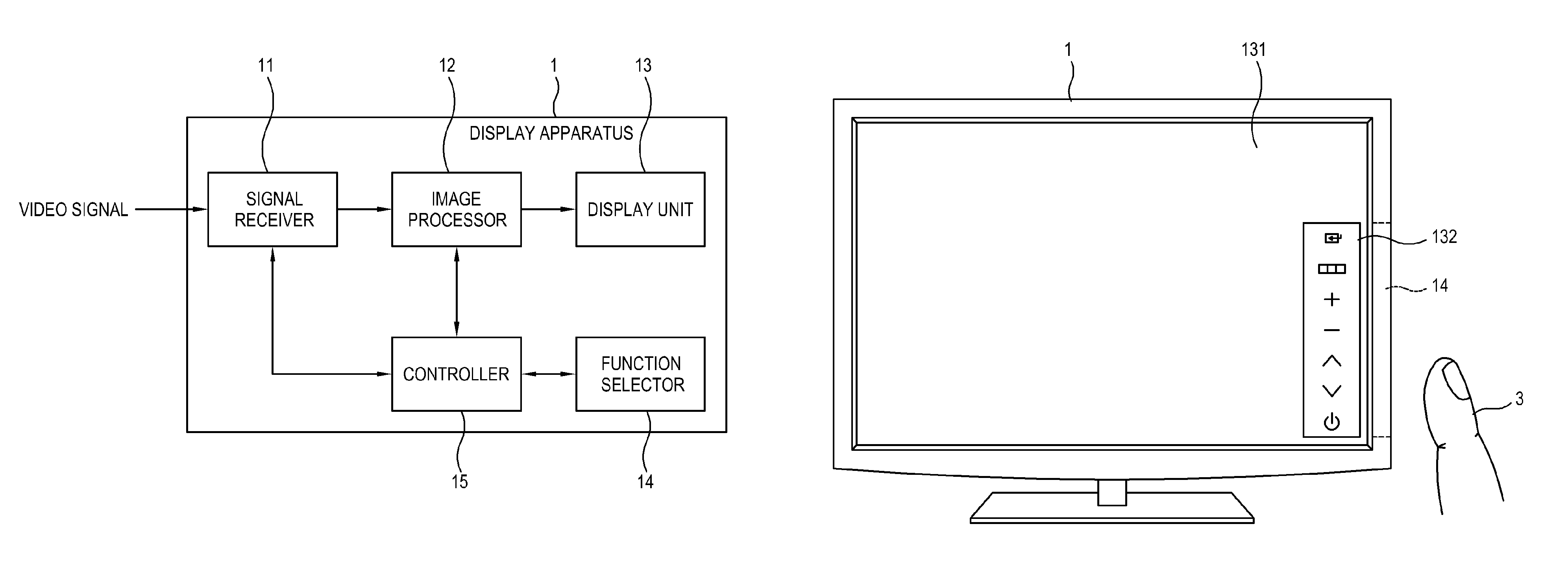
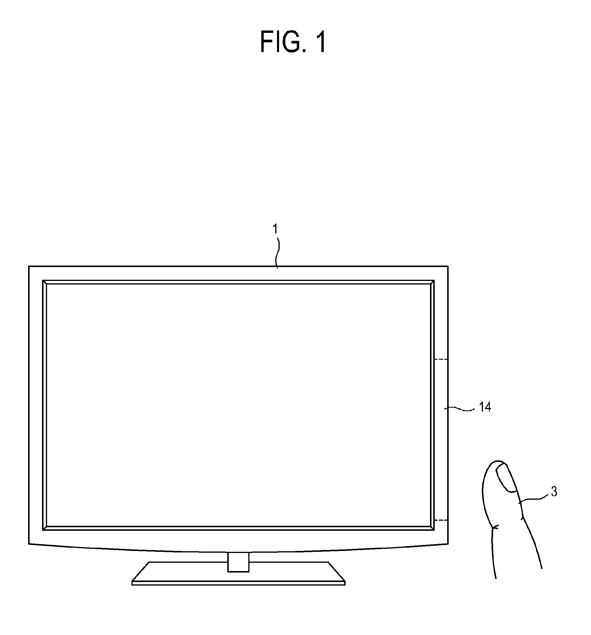
[0059]FIG. 1 shows a display apparatus 1 according to an exemplary embodiment. The display apparatus 1 shown in FIG. 1 is a television (TV). However, the display apparatus is not limited to the TV, but includes any imaging or a display device which can perform a plurality of functions and provide a user interface for the functions or for operating the device.

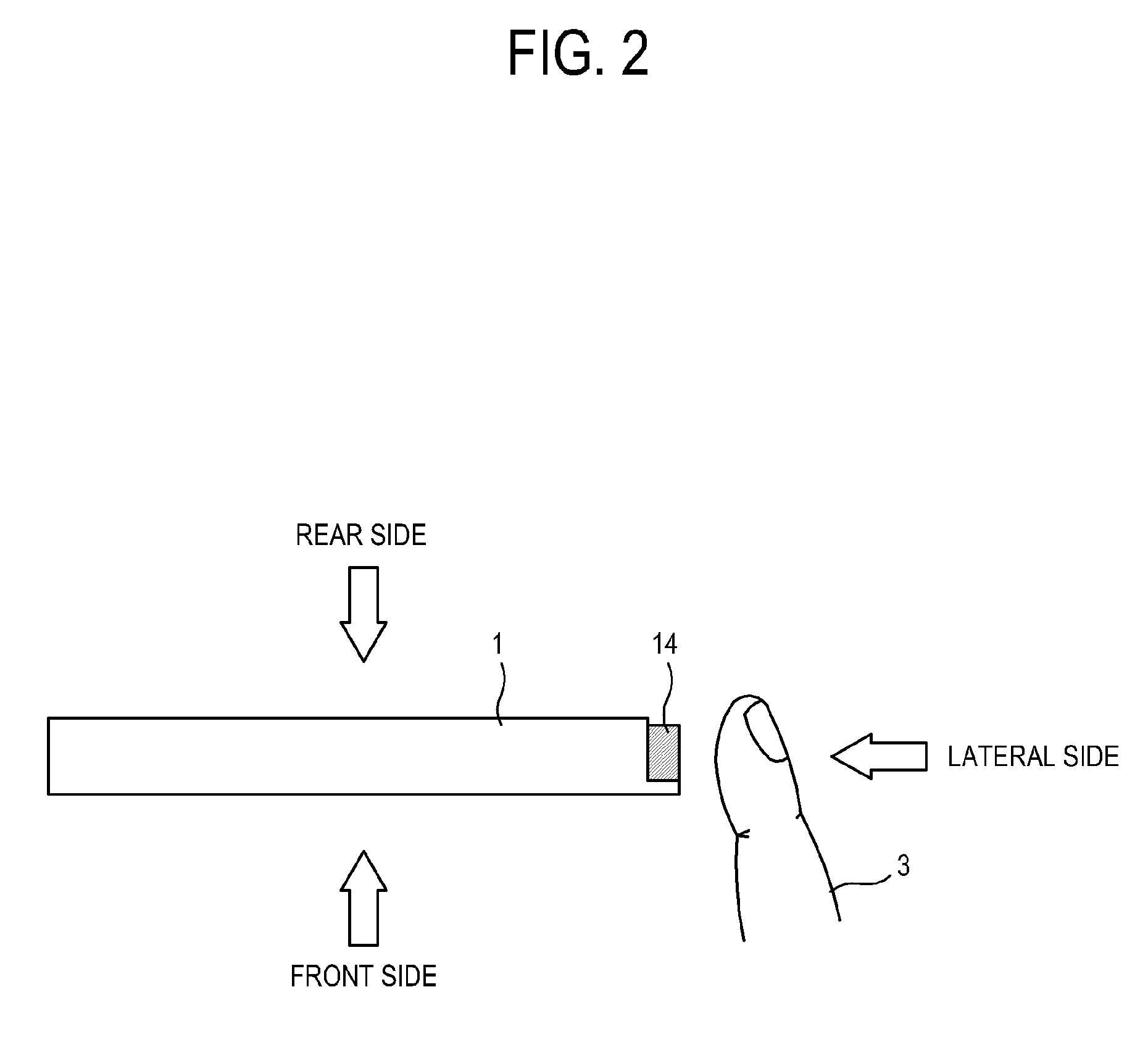
[0060]The display apparatus 1 performs a plurality of functions such as power on or off, screen adjustment, etc., as well as image display. The display apparatus 1 includes a user interface 14 for allowing a user to select the plurality of functions, e.g., for receiving user input. The user interface 14 may be provided on a front side (FIG. 1), a lateral side (FIG. 2) or the like of the display apparatus 1. FIG. 2 is a top view of the display apparatus of FIG. 1. A user can select a desired function among the plurality of funct...


PUM


Abstract

Disclosed are a display apparatus and a control method thereof, the display apparatus including: a signal receiver which receives a video signal; an image processor which processes the video signal received by the signal receiver; a display unit which displays an image on the basis of the video signal processed by the image processor; a function selector which senses a user's operation for selecting a plurality of functions provided by the display apparatus; and a controller which displays an on screen display (OSD) menu for selecting the plurality of functions on the display unit in accordance with a user's first operation entering within a predetermined distance from the function selector, and operates one selected among the plurality of functions in accordance with a user's second operation. With this, it is possible to provide an intuitive, convenient and reliable user interface for selecting a plurality of functions even under spatial limitations.

Description

CROSS-REFERENCE TO RELATED APPLICATION[0001]This application claims priority from Korean Patent Application No. 10-2011-0019360, filed on Mar. 4, 2011 in the Korean Intellectual Property Office, the disclosure of which is incorporated herein by reference.BACKGROUND[0002]1. Field[0003]Apparatuses and methods consistent with the exemplary embodiments relate to a display apparatus and a control method thereof, and more particularly, to a display apparatus providing a user interface for selecting a plurality of functions and a control method thereof.[0004]2. Description of the Related Art[0005]A display apparatus such as a television (TV), a monitor for a personal computer (PC), etc. provides a user interface for allowing a user to control operations (hereinafter, referred to as a ‘function’) to be implemented. The functions of the display apparatus may include power on / off, channel change, screen adjustment, volume control, etc. The user interface for controlling such functions of the ...

Claims


Application Information

Patent Timeline
Patent Type & Authority Patents(United States)
IPC IPC(8): H04N5/445H04N5/50
CPCH04N21/42201H04N21/4312H04N21/485H04N5/44H04N5/445H04N5/44504H04N21/47
Inventor KANG, KEUN-SEOKLEE, SUNG-HANYANG, SUN-HO
Owner SAMSUNG ELECTRONICS CO LTD
Learn More