Bearing mechanism, motor and disk drive apparatus

a bearing mechanism and disk drive technology, applied in the field of bearing mechanisms, can solve the problems of inability to introduce lubricant to inability to fill lubricant from the lower seal gap, etc., and achieve the effect of easy filling of lubricant into the bearing mechanism

Inactive Publication Date: 2013-11-19
NIPPON DENSAN CORP
View PDF55 Cites 11 Cited by
  • Summary
  • Abstract
  • Description
  • Claims
  • Application Information

AI Technical Summary

Benefits of technology

The technical effect of this innovation makes filling bearings with oil easier than ever before by creating an opening between them through which the grease can be added without having any problems or inconvenience for maintenance workers.

Problems solved by technology

The technical problem addressed in this patent is the difficulty of filling a lubricant into a bearing mechanism of a motor used in a disk drive apparatus. In conventional motors, the upper seal gap is covered by the rotor, preventing the lubricant from reaching the lower seal gap. This results in the need for a new bearing mechanism that allows for easy lubricant filling from an upper seal gap.

Method used


Image

  • Bearing mechanism, motor and disk drive apparatus
  • Bearing mechanism, motor and disk drive apparatus
  • Bearing mechanism, motor and disk drive apparatus

Examples


Embodiment Construction

[0028]In the following description, the upper side of a motor in a center axis direction will be just referred to as “upper” and the lower side as “lower”. The up-and-down direction is not intended to indicate the positional relationship or the orientation when the motor is installed within an actual device. The direction parallel or substantially parallel to the center axis will be referred to as “axial”. The radial direction about the center axis will be just referred to as “radial”. The circumferential direction about the center axis will be just referred to as “circumferential”.

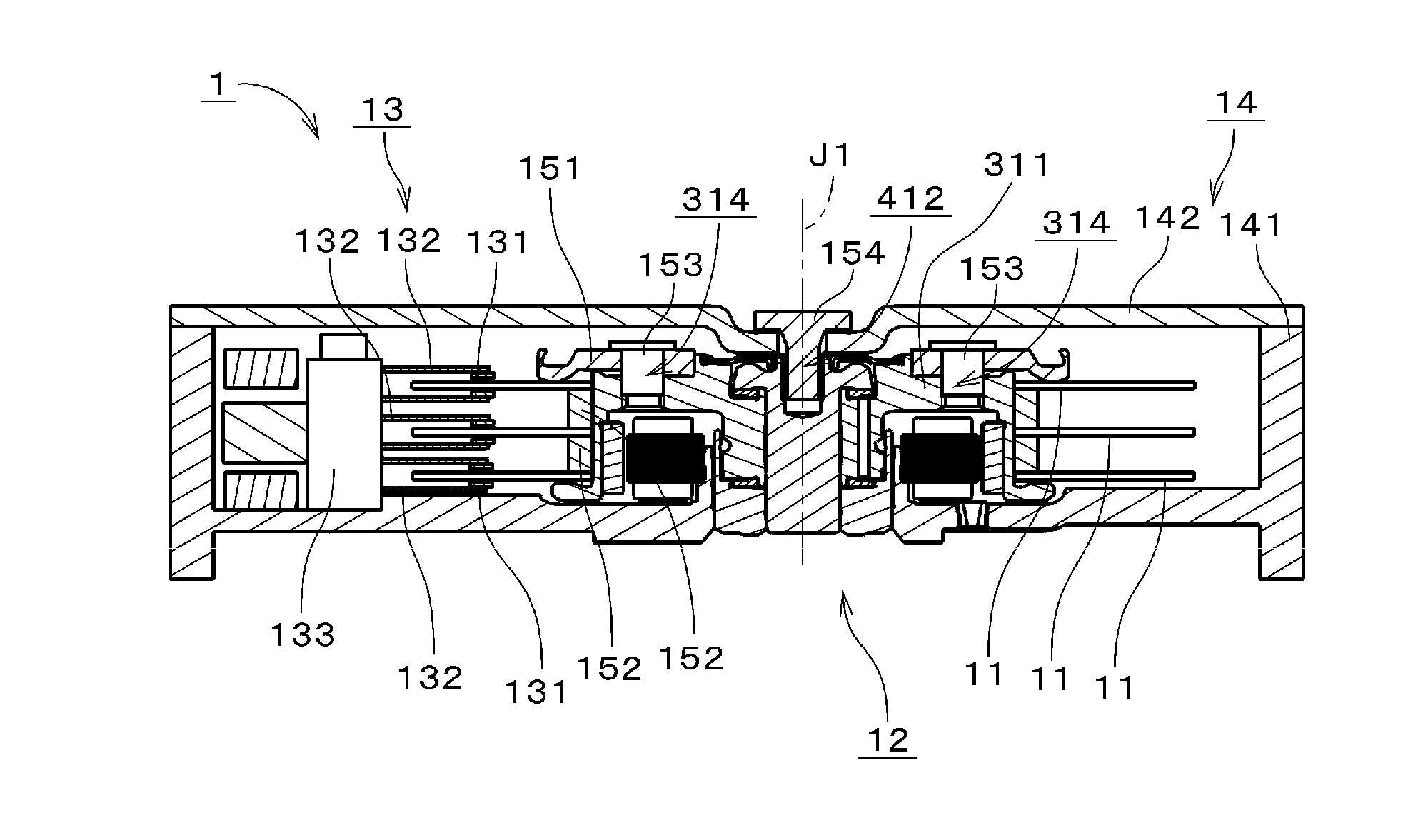
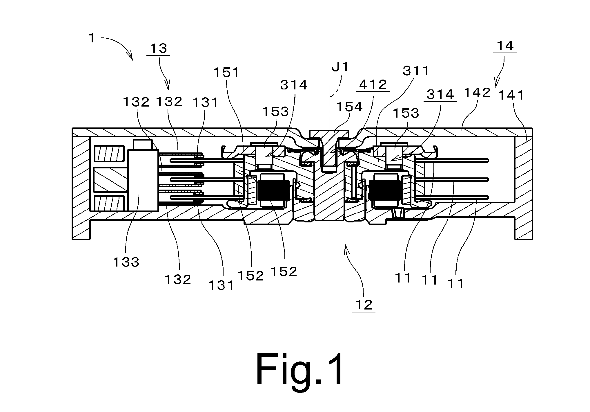
[0029]FIG. 1 is a vertical sectional view of a disk drive apparatus 1 including a spindle motor (hereinafter just referred to as “motor”) according to one illustrative preferred embodiment of the present invention. The disk drive apparatus 1 is preferably a so-called hard disk drive apparatus. The disk drive apparatus 1 preferably includes, e.g., three disks 11, a motor 12, an access unit 13, and a housin...


PUM


Abstract

A bearing mechanism includes a shaft portion, a sleeve portion, a lower opposing portion, a lower outer ring-shaped portion, and an upper opposing portion. A lower seal portion serving as a pumping seal portion is provided in a lower seal gap between the sleeve portion and the lower outer ring-shaped portion. An upper seal portion is provided in an upper seal gap joined to an upper thrust gap. The lower portion of the sleeve portion includes a large-diameter portion and a small-diameter portion positioned below the large-diameter portion. The sleeve portion includes a communication path joined to the upper seal gap. The communication path includes an opening portion opened in a border between the large-diameter portion and the small-diameter portion. The outer peripheral portion of the lower opposing portion includes an outer periphery protrusion portion radially opposed to the small-diameter portion and axially opposed to the large-diameter portion.

Description


Claims


Application Information

Patent Timeline
Owner NIPPON DENSAN CORP
Why Eureka
Try Eureka