Dipper door latch with locking mechanism

a technology of latches and dippers, which is applied in the direction of fastening means, mechanical machines/dredgers, constructions, etc., can solve the problems of constant replacement of ropes, broken pull chains and clevises, and significant maintenance costs of dipper latches and related operating equipment, so as to reduce lubricated rotational friction and less force

Inactive Publication Date: 2013-11-26
JOY GLOBAL SURFACE MINING INC
View PDF14 Cites 20 Cited by
  • Summary
  • Abstract
  • Description
  • Claims
  • Application Information

AI Technical Summary

Benefits of technology

[0009]The amount of tension required to trip or move a latch bar on a fully loaded 120-ton payload dipper nearly exceeds the mechanical ability of this system. Larger motors are usually the solution, but the net result is a very high cost maintenance area.
[0018]The latch mechanism eliminates almost all dry sliding contact surfaces by replacing translational sliding motion with rotational motions, and replaces the dry sliding latch bar approach with a new rotational door latch where there are no members that see high loads and dry sliding friction at the same time. Dry sliding friction is replaced with greatly decreased lubricated rotational friction. Members rotate relative to each other and the dipper but the rotation does not take place while undergoing high loads. This reduces the extremely high stresses present in conventional latch mechanisms to a magnitude that requires significantly less force to actuate.

Problems solved by technology

There are maintenance problems with this system, especially when it is used with 100-ton or larger payload dippers.
Latch bars and related operating equipment are a significant part of dipper maintenance cost.
The maintenance problems include broken pull chains and clevis.
The trip ropes have to be replaced constantly as they become frayed and strands break.
The tugger motor, gearing and drum take a continuous beating causing repeated failures.
And lastly, the latch bar has to have shimming added, and this is a constant ongoing maintenance issue that in the long run becomes labor intensive and costly.
The amount of tension required to trip or move a latch bar on a fully loaded 120-ton payload dipper nearly exceeds the mechanical ability of this system.
Larger motors are usually the solution, but the net result is a very high cost maintenance area.
There are also operational problems with the existing latch system that adversely affect shovel production and safety.
The dry, sliding friction that the latch lever must overcome for successful unlatching is unpredictable.
This adversely affects production as it requires extra time to complete a dig cycle.
On the other extreme, exposure to water, mud, or manual lubrication of the existing sliding latch reduces the friction forces to such an extent that the tripping effort becomes very sensitive to inadvertent trip rope line pulls.
As a result, “false” trips can occur, which causes the dipper door to open at times the operator does not want it to.
This is dangerous because the dipper opens before it is fully swung over the truck, potentially dropping its entire payload on the surrounding area.
This is also inconvenient and nonproductive as the operator must then refill the dipper and complete a new dig cycle.

Method used


Image

  • Dipper door latch with locking mechanism
  • Dipper door latch with locking mechanism
  • Dipper door latch with locking mechanism

Examples


first embodiment

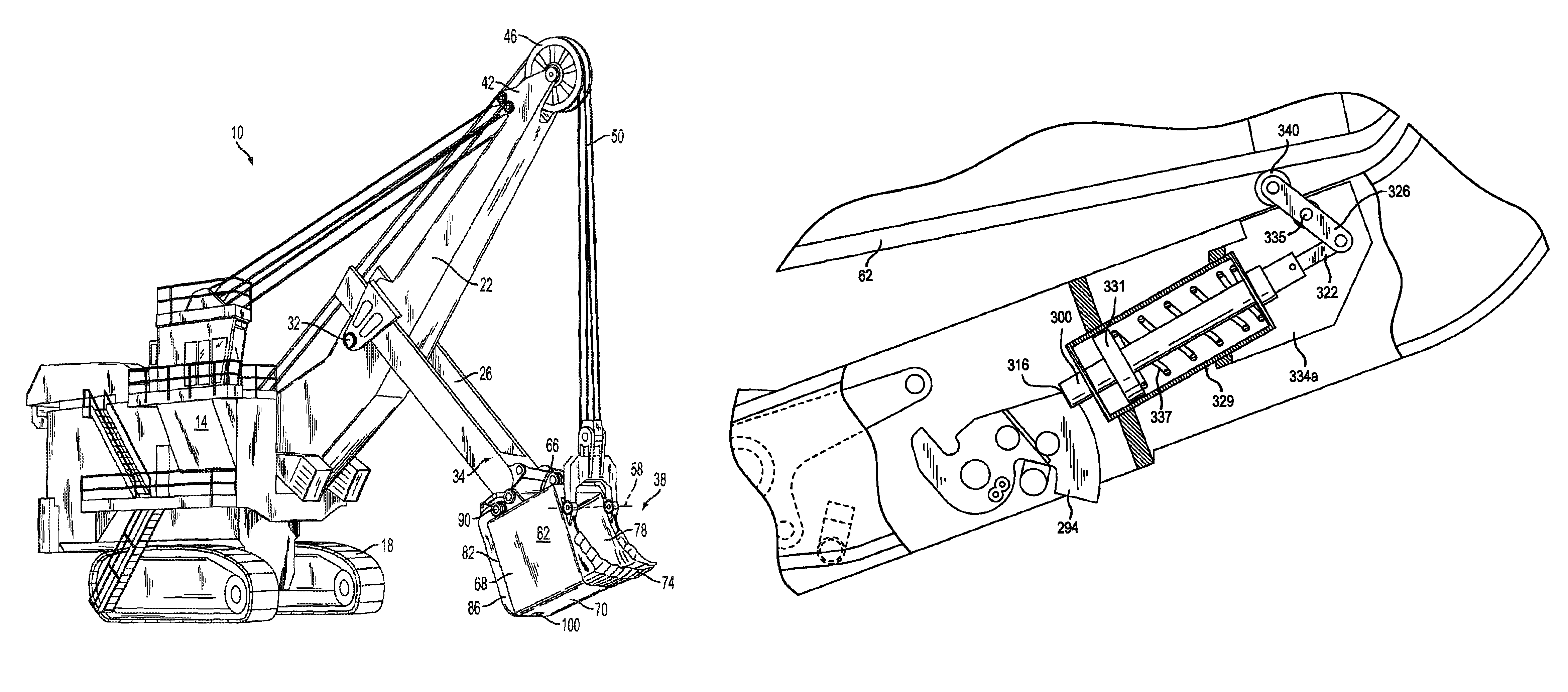
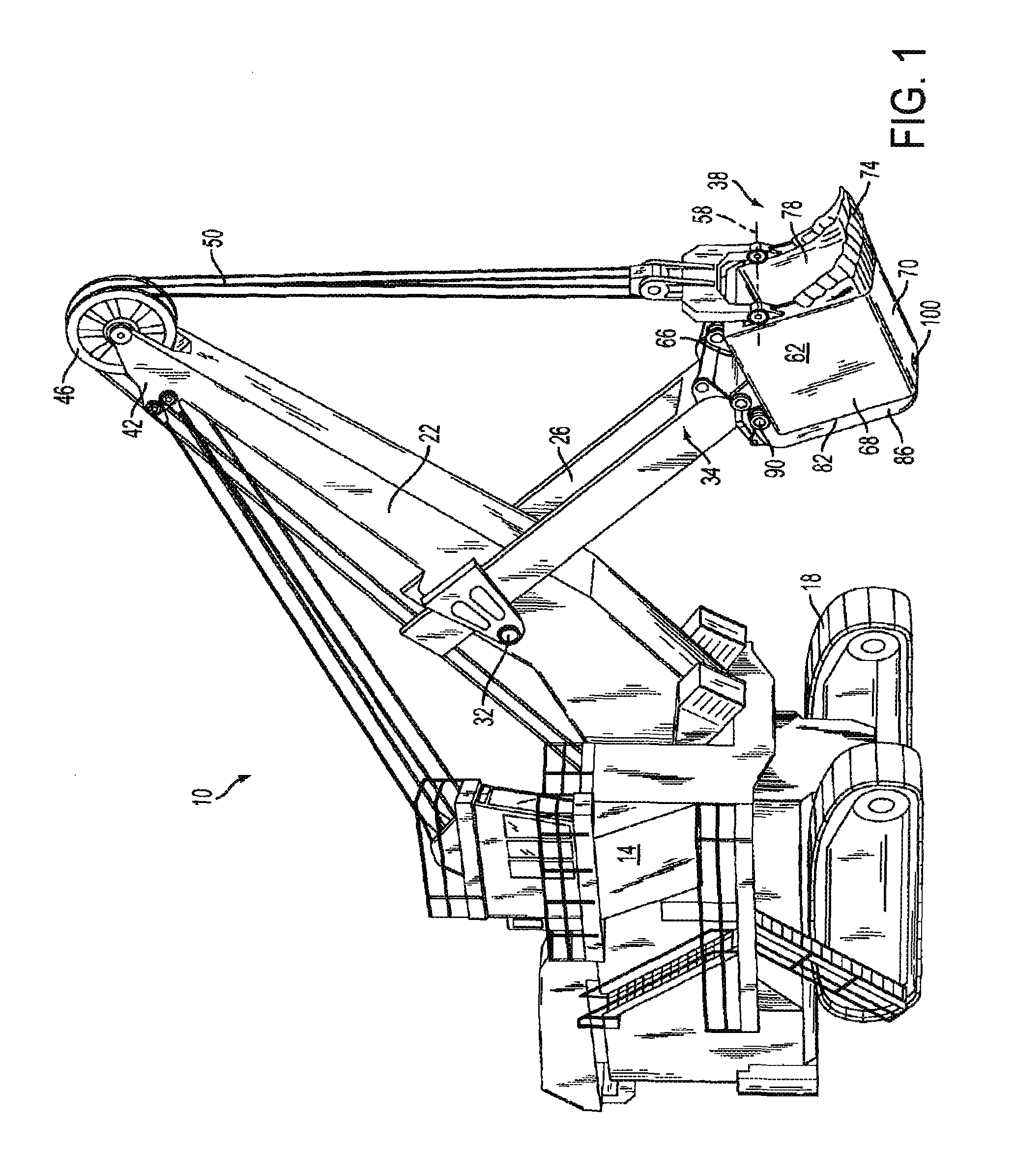
[0054]In one embodiment, as illustrated in FIGS. 5, 6 and 7, the hold open mechanism 120 and locking mechanism 124 is a hydraulic cylinder assembly 128 pivotally attached to and extended between the dipper door 86 and the latch jaw 104. More particularly, as illustrated in FIGS. 5 and 6, the hydraulic cylinder assembly 128 is pivotally attached at one end between two of the support ribs 116.

[0055]The hydraulic assembly 128 is provided with a hydraulic cylinder 132 and a piston 134 that is movable within the hydraulic cylinder 132. The piston 134 divides the hydraulic cylinder 132 into a first chamber and a second chamber wherein the volumes of the chambers change as the piston 134 moves back and forth within the hydraulic cylinder 132. Either the hydraulic cylinder 132 or the piston 134 can be connected to the latch and the other connected to the dipper door 86.

[0056]More particularly, in this embodiment (as shown in FIG. 7), the hold open mechanism 120 and locking mechanism 124 inc...

second embodiment

[0061]In another embodiment, shown in FIGS. 9 through 16, like numerals identify items described previously. As illustrated in FIGS. 11 and 12, the locking mechanism 124 in this embodiment includes a primary locking mechanism 160 including one bar 164 pivotally attached at 165 to the door 86, and another connecting bar 168 pivotally connected to and extending between each of the one bar 164 at 166 and the latch jaw 104 at 167. The latch jaw 104 is pivotally connected to the door 86 at 169. Further, the hold open mechanism 120 in this embodiment is means biasing the latch jaw 104 into its open position in the form of a tension spring 172 attached between the one bar 164 and the connecting bar 168. More particularly, in this embodiment, there is one spring 172 on one side of the one bar 164 and the connecting bar 168 and a similar spring (see FIG. 12) on the opposite side of the one bar 164 and the connecting bar 168. When locking the locking mechanism 124, the pivot connection 166 be...

third embodiment

[0084]A further and preferred embodiment of the latch mechanism is illustrated in FIG. 18. In this embodiment, additional bumper stops have been added. More particularly, a bumper stop 201a has been added to the top protective cover 173, and another bumper stop 201c has been added to the dipper door 86 underneath the bar end 200, so that as the pivot connection 166 between the two bars moves, the ends of travel contact the bumper stops 201a and 201c, and absorb energy within the pivot connection 166. Furthermore, a bumper stop 201d has been added to the top of the bar 164 so that, when the bar 164 contacts the upper protective cover 173, energy is absorbed by the bumper stop 201d.

[0085]In another and preferred embodiment, the secondary latch mechanism further includes a false latch preventing mechanism 298, shown in FIG. 21. More particularly there are times where, when material hits the latch jaw 104, the latch mechanism may rotate to the latch closed position even though the dipp...


PUM


Abstract

A dipper including a dipper door and an impact actuated jaw having a “C” shape defining a lip and a chin. The jaw is rotatably mounted on the dipper door for rotation between a door-opened position and a door-closed position and positioned so that when the jaw is in the door-opened position, the jaw chin can be impacted by the dipper body when the door pivots to the door-closed position. The dipper also includes a hold open mechanism for releasably holding the door latch in the latch open position when the latch is in the open position, and a locking mechanism for releasably locking the latch when the latch is in the door-closed position. The locking mechanism includes one bar pivotally attached to the door, and another bar pivotally connected to and extending between each of the one bar and the latch.

Description

CROSS REFERENCE TO RELATED APPLICATIONS[0001]This application is a continuation-in-part of application Ser. No. 12 / 684,883, filed on Jan. 8, 2010, which is a continuation-in-part of application Ser. No. 11 / 608,307, filed on Dec. 7, 2006, which is a continuation-in-part of application Ser. No. 11 / 457,141, filed Jul. 12, 2006, which claims the benefit of U.S. Provisional Application No. 60 / 698,797 filed Jul. 13, 2005, the entire contents of which are incorporated herein by reference.TECHNICAL FIELD[0002]The present invention relates to power shovels and, more particularly, to power shovels having a dipper adapted for excavating earthen material. Specifically, the present invention relates to latches for dipper doors.BACKGROUND OF THE INVENTION[0003]Large electric mining rope shovels utilize a digging attachment consisting of a stationary boom with a combination handle / dipper structure which mounts on the boom and actively crowds and hoists into a bank in order to dig with and fill the...

Claims


Application Information

Patent Timeline
Patent Type & Authority Patents(United States)
IPC IPC(8): E02F3/30
CPCE02F3/4075E02F3/46E02F3/60E02F9/2883E02F3/308Y10T292/1048Y10T292/47
Inventor HREN, WILLIAM J.COLWELL, JOSEPH J.SCHWAKE, JEFFREY S.KEARSLEY, BRUCE P.
Owner JOY GLOBAL SURFACE MINING INC
Why Eureka
Try Eureka