Bending device for endoscope

a technology of endoscope and bending device, which is applied in the field of bending device of endoscope, can solve the problems of inability to ensure the space in which various members are inserted, the difficulty of forming a lancing arch portion, distortion or damage, etc., and achieves the effect of reducing the diameter increasing the filling rate of the inserting member, and not very high resistance to bending

Inactive Publication Date: 2013-11-26
FUJIFILM CORP
View PDF14 Cites 7 Cited by
  • Summary
  • Abstract
  • Description
  • Claims
  • Application Information

AI Technical Summary

Benefits of technology

[0009]The invention is accomplished in view of the aforementioned respects. An object of the invention is to accurately guide an operating wire in a bendable tube portion even in a case where no lancing arch portion, which is difficult to process and may reduce the strength of a bending piece, is provided on the bending piece.
[0013]Accordingly, a part of the flexible sleeve, in which the operating wire is inserted, extends between the base-end-side fixed portion, which is fixed in the main-body operating portion or to the position of the base end part of the flexible tube portion, and the tip-end-part-side fixed portion, which is fixed to the connection portion between the flexible tube portion and the bendable tube portion, constitutes a remote control cable for accurately transmitting to a tip end part an amount of pushing and pulling the operating wire. That is, the flexible portion is a part freely bending along an insertion path. In this part, the operating wire and the flexible sleeve constitute a remote control cable. This remote control cable has an extra length in the flexible tube portion.
[0014]The bendable tube portion is held in a straight state, as long as an operating force or an external force is not acted thereon. It is unnecessary that the bendable tube portion has an extra length in this part. The bendable tube portion is extended from the tip-end-side fixed portion of the flexible sleeve. This extension portion does not constitute a remote control cable. The extension portion serves to position and guide the operating wire so that the operating wire is neither deviated nor displaced in the circumferential direction in the bendable tube portion. The operating wire is pushed and pulled in the insertion portion. Various members, such as an optical fiber and a signal cable, are inserted in the insertion portion, in addition to the operating wire. Therefore, to prevent the operating wire from being damaged due to the relative sliding movement of the operating wire and the various inserting members, these elements are covered with the flexible sleeve. Thus, the operating wire can be moved in the flexible sleeve in the direction of pushing and pulling thereof.

Problems solved by technology

Thus, it is difficult to form a lancing arch portion with respect to which the operating wire inserted in the small-sized bending piece can smoothly slide.
When an external pressing force acts upon the bendable tube portions a distortion or damage may occur.
However, in such a case, a space, in which various members are inserted cannot be assured.
Thus, the inserting member may be damaged.
Thus, the degree of risk of damage is further increased.

Method used


Image

  • Bending device for endoscope
  • Bending device for endoscope
  • Bending device for endoscope

Examples


Embodiment Construction

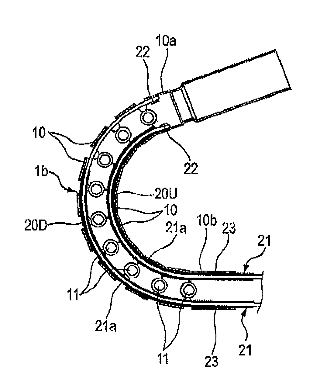
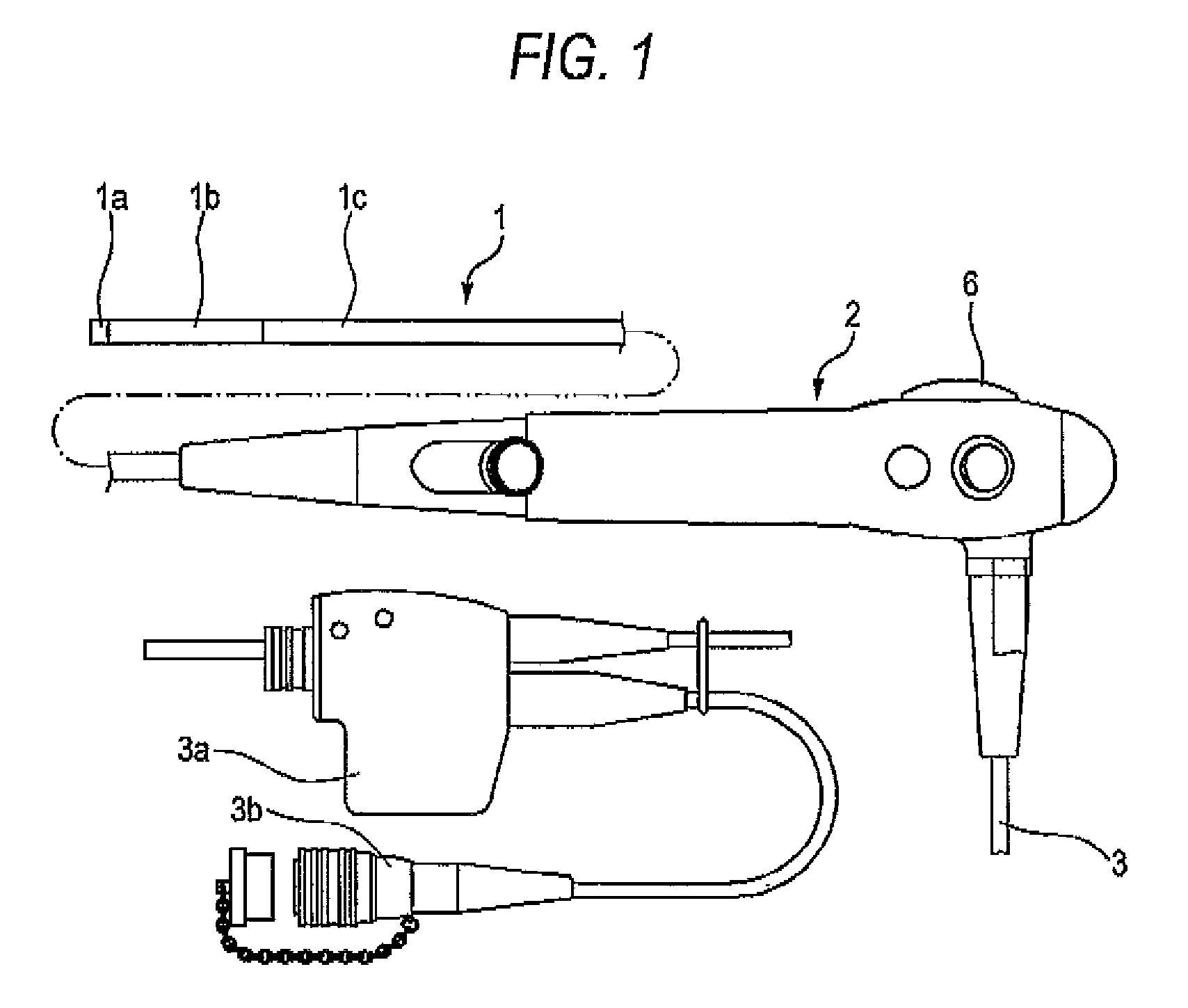
[0024]Hereinafter, an embodiment of the invention is described with reference to the accompanying drawings. FIG. 1 illustrates the configuration of the entire endoscope. In FIG. 1, reference numeral 1 designates an insertion portion. Reference numeral 2 denotes a main-body operating portion. Reference numeral 3 represents a universal cord. The insertion portion 1 includes a rigid tip end portion 1a, a bendable tube portion 1b and a flexible tube portion 1c, which are arranged in order from a tip end side. The main-body operating portion 2 is provided by being coupled to a base end part of the flexible tube portion 1c, so that an operator for the endoscope holds and operates the main-body operating portion 2 by hand. The universal cord 3 extends from the main-body operating portion 2 and has connectors 3a and 3b so as to be detachably connected to a light source apparatus and a processor.

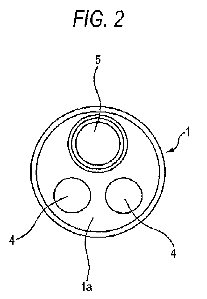
[0025]As illustrated in FIG. 2, an endoscope observation section including two illumination porti...


PUM


Abstract

An operating wire is inserted in a close-contact coil in a bendable tube portion through a flexible tube portion. The close-contact coil is such that a fixed portion is provided at the position of a bending piece which is placed at the most base end of the bendable tube portion, and that a close-contact coil extension portion having been put in a non-fixed state extends from the fixed portion in the bendable tube portion. A part between a fixed portion and the fixed portion of the close-contact coil is a remote control cable for transmitting an amount of pushing and pulling an operating wire when operating an operating wire. A close-contact coil extension portion extended from the fixed portion at the side of a tip end of the close-contact coil functions as a positioning guide section for holding the operating wire so as to prevent the operating wire from being displaced in a circumferential direction.

Description

BACKGROUND OF THE INVENTION[0001]1. Field of the Invention[0002]The present invention relates to a bending device of an endoscope, which is remotely operated by a main-body operating portion to bend a curved portion provided in an insertion portion of the endoscope to be used in medical practices or the like.[0003]2. Description of the Related Art[0004]A related endoscope is configured so that a base end part of an insertion portion to be inserted into a body cavity is coupled to a main-body operating portion. The insertion portion has a rigid tip end portion, a bendable tube portion, and a flexible tube portion arranged in order from a tip end side. An endoscope observation section having at least an illumination portion and an observation portion is provided in the rigid tip end portion. The bendable tube portion can be bent by remote control from the main-body operating portion so as to direct the rigid tip end portion in a predetermined direction. The bendable tube portion is co...

Claims


Application Information

Patent Timeline
Patent Type & Authority Patents(United States)
IPC IPC(8): A61B1/00
CPCA61B1/0057
Inventor YAMAZAKI, MASAYUKI
Owner FUJIFILM CORP
Why Eureka
Try Eureka