Prosthetic valve for intraluminal implantation

a technology for prosthetic valves and intraluminal implantation, which is applied in the field of prosthetic valves for intraluminal implantation, can solve the problems of affecting the life of the valve, the support of the stent must be very long to prevent migration, and the failure of the valve along the millions of cycles

a technology for prosthetic valves and intraluminal implantation, which is applied in the field of prosthetic valves for intraluminal implantation, can solve the problems of affecting the life of the valve, the support of the stent must be very long to prevent migration, and the failure of the valve along the millions of cycles

US8591573B2Inactive Publication Date: 2013-11-26BARONE

Image

  • Prosthetic valve for intraluminal implantation
  • Prosthetic valve for intraluminal implantation
  • Prosthetic valve for intraluminal implantation

Examples


Embodiment Construction

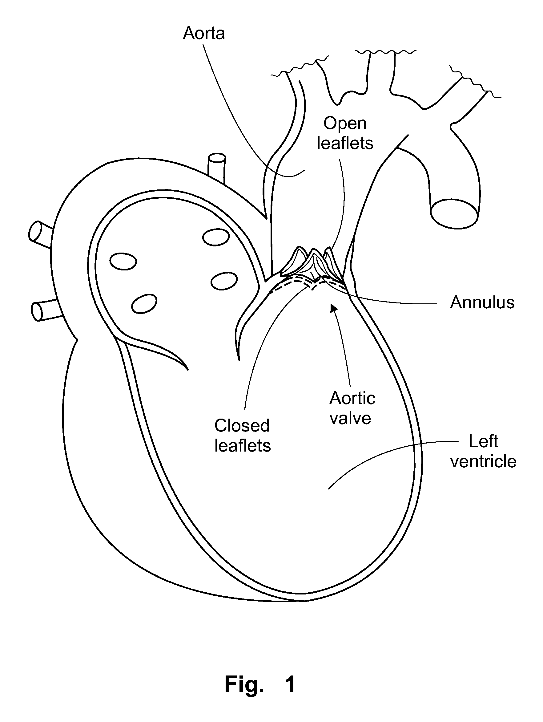
[0034]Now referring in detail to the drawings, FIG. 1 shows a cross sectional view of a human heart wherein an aortic valve is shown for permitting blood flow from the ventricle towards the aorta and to prevent backflow. The normal valve is a tricuspid valve with three leaflets or cusps that move upwardly to open the valve, as shown in solid lines, and downwardly to close the valve as shown in phantom lines. When this natural valve is deficient or defective it must be repaired or replaced by a prosthetic valve.

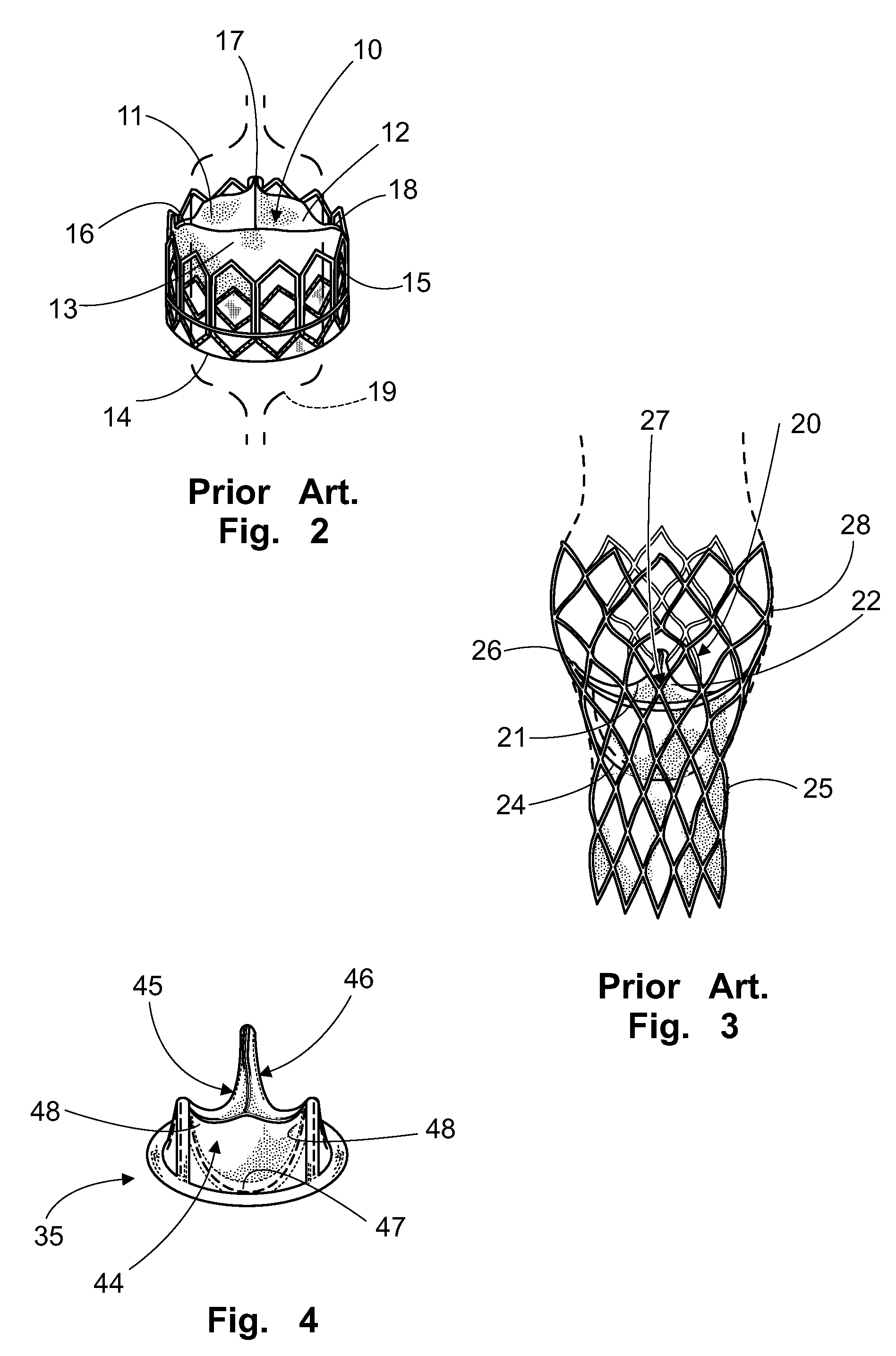
[0035]FIG. 2 shows a prosthetic valve of the prior art comprising a central valve 10 comprising three leaflets or cusps 11, 12, 13, all made of any suitable natural or synthetic flexible material. By any proper means a base 14 of the central valve is affixed to a valve support 15 made of any suitable balloon-expandable material configured to be capable of being expanded and anchored by radial expansion against a lumen, such as the aortic root, of the patient, more precisely th...


PUM


Abstract

A prosthetic valve assembly configured to be intraluminally implanted into a lumen of a patient to replace a native deficient valve, the valve assembly comprising an outer support for expanding and anchoring against a lumen wall of the patient, a core valve support made of a collapsible and self-expanding material to expand and anchor into the outer support once anchored against the lumen wall, and a plurality of flexible leaflets fixed to the core valve support in a manner that the leaflets are independent from the outer support.

Description

BACKGROUND OF THE INVENTION[0001]1. Field of the Invention[0002]The present invention relates to the field of prosthetic medical devices for implantation into a patient and more particularly refers to a valve assembly configured to be intraluminaly delivered into a lumen of a vessel of a patient and assembled at a location into the lumen where a native valve of the patient is deficient.[0003]2. Description of the Prior Art[0004]It has been a practice to open the thorax of a patient when a defective corporeal valve had to be repaired. Particularly in cardiac valves, the traditional surgery has been a very risky procedure involving the steps of opening the thorax, providing extracorporeal blood circulation, and surgically opening the heart to remove the defective valve and implanting a new one, namely a prosthetic valve generally sutured into the blood vessel having the deficient natural or native valve.[0005]In the last years, a less risky and less invasive technique has consisted of...

Claims


Application Information

Patent Timeline
26 Nov 2013
Publication
US8591573B2
IPC
A61F2/06; A61F2/24
CPC
A61F2/2418; A61F2250/0069; A61F2220/0008; A61F2220/0016; A61F2220/0075; A61F2230/0054; A61F2230/008; A61F2250/006
Inventors
BARONE, HECTOR DANIEL