Monitoring system

a monitoring system and impedance measurement technology, applied in the field of impedance measurement methods and apparatuses, can solve the problems of inductive coupling and the impact of the impedance measurement process accuracy, and achieve the effect of reducing imbalan

Active Publication Date: 2013-11-26
IMPEDIMED
View PDF282 Cites 3 Cited by
  • Summary
  • Abstract
  • Description
  • Claims
  • Application Information

AI Technical Summary

Benefits of technology

[0062]Typically the method includes, in the processing system, determining the modified first signal so as to minimise the imbalance.
[0123]i) extend from the measuring device in different directions to thereby reduce inductive coupling therebetween; and,
[0152]i) extend from the measuring device in different directions to thereby reduce inductive coupling therebetween; and,
[0173]i) extend from the measuring device in different directions to thereby reduce inductive coupling therebetween; and,
[0189]i) extend from the measuring device in different directions to thereby reduce inductive coupling therebetween; and,
[0205]i) extend from the measuring device in different directions to thereby reduce inductive coupling therebetween; and,

Problems solved by technology

In such arrangements, one source of noise results from inductive coupling between the first and second leads.
This induced current interferes with the measurement of the induced voltage, which can in turn impact on the accuracy of the impedance measurement process.

Method used


Image

  • Monitoring system
  • Monitoring system
  • Monitoring system

Examples


Embodiment Construction

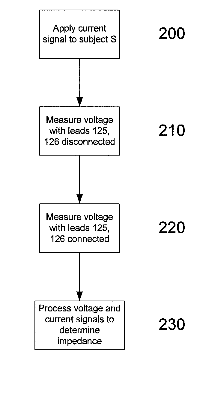
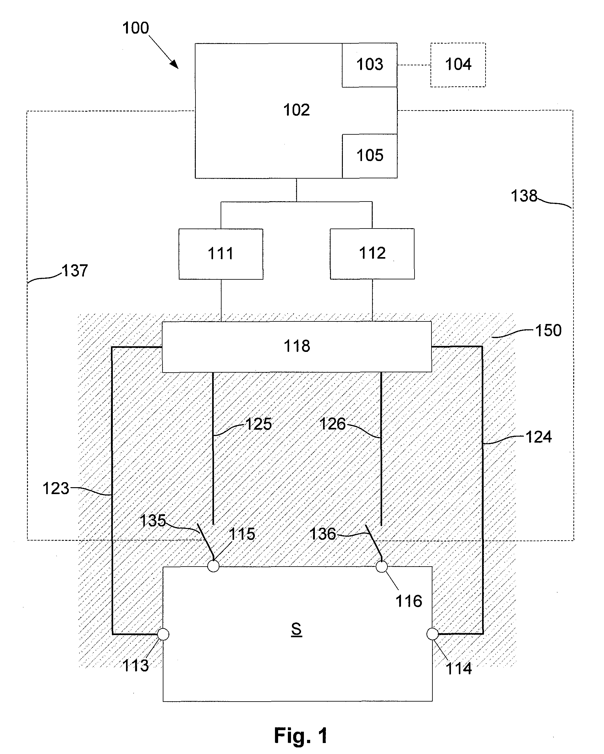
[0248]An example of apparatus suitable for performing an analysis of a subject's bioelectric impedance will now be described with reference to FIG. 1.

[0249]As shown the apparatus includes a measuring device 100 including a processing system 102 coupled to a signal generator 111 and a sensor 112. In use the signal generator 111 and the sensor 112 are coupled to first electrodes 113, 114, and second electrodes 115, 116, provided on a subject S, via respective first leads 123, 124, and second leads 125, 126. The connection may be via a switching device 118, such as a multiplexer, allowing the leads 123, 124, 125, 126 to be selectively interconnected to signal generator 111 and the sensor 112.

[0250]In this example, the second leads 125, 126 are connected to the second electrodes 115, 116, via respective switches 135, 136. In use, the switches 135, 136 can be controlled by the processing system 102 using suitable wired or wireless control connections, shown generally by dotted lines at 1...


PUM


Abstract

A method for performing impedance measurements on a subject. The method includes, in a processing system, causing at least one electrical signal to be applied to the subject via first leads operatively connected to first electrodes provided on the subject, determining a first indication indicative of at least one first electrical signal measured via second leads operatively disconnected from second electrodes positioned on the subject, determining a second indication indicative of at least one second electrical signal measured via second leads operatively connected to second electrodes positioned on the subject, and determining from the indications and the at least one applied signal, at least one instantaneous impedance value.

Description

BACKGROUND OF THE INVENTION[0001]The present invention relates to a method and apparatus for performing impedance measurements.DESCRIPTION OF THE PRIOR ART[0002]The reference in this specification to any prior publication (or information derived from it), or to any matter which is known, is not, and should not be taken as an acknowledgment or admission or any form of suggestion that the prior publication (or information derived from it) or known matter forms part of the common general knowledge in the field of endeavour to which this specification relates.[0003]One existing technique for determining biological parameters relating to a subject involves the use of bioelectrical impedance. This involves applying electrical signals to a subject and then measuring signals induced within the subject, using a series of electrodes placed on the skin surface, allowing the electrical impedance of the subject's body to be determined. This information can then be used to derive parameters indic...

Claims


Application Information

Patent Timeline
Patent Type & Authority Patents(United States)
IPC IPC(8): A61B5/00
CPCA61B5/0537A61B5/4869A61B5/4878A61B5/6829A61B5/6824
Inventor CHETHAM, SCOTT
Owner IMPEDIMED
Why Eureka
Try Eureka